
Hydrodynamic capture and release mechanisms for particle manipulation

Inactive Publication Date: 2006-06-15
GERHARDT ANTIMONY L +6
View PDF17 Cites 161 Cited by
  • Summary
  • Abstract
  • Description
  • Claims
  • Application Information

AI Technical Summary

Benefits of technology

[0014] According to one aspect of the present invention, the particulate analysis and sorting apparatus has an array of geometric sites for capturing particulates traveling along a fluid flow. The geometric sites are arranged in a defined pattern across a substrate such that individual sites are known and identifiable. Each geometric site is configured and dimensioned to hold a single particulate. Additionally, each site contains a release mechanism to selectively release the single particulate from that site. Because each site is able to hold only one particulate, and each site has a unique address, the apparatus allows the user to know the location of any particular particulate that has been captured. Further, each site is independently controllable so that the user is able to arbitrarily capture particulates at select locations, and to release particulates at various locations across the array.
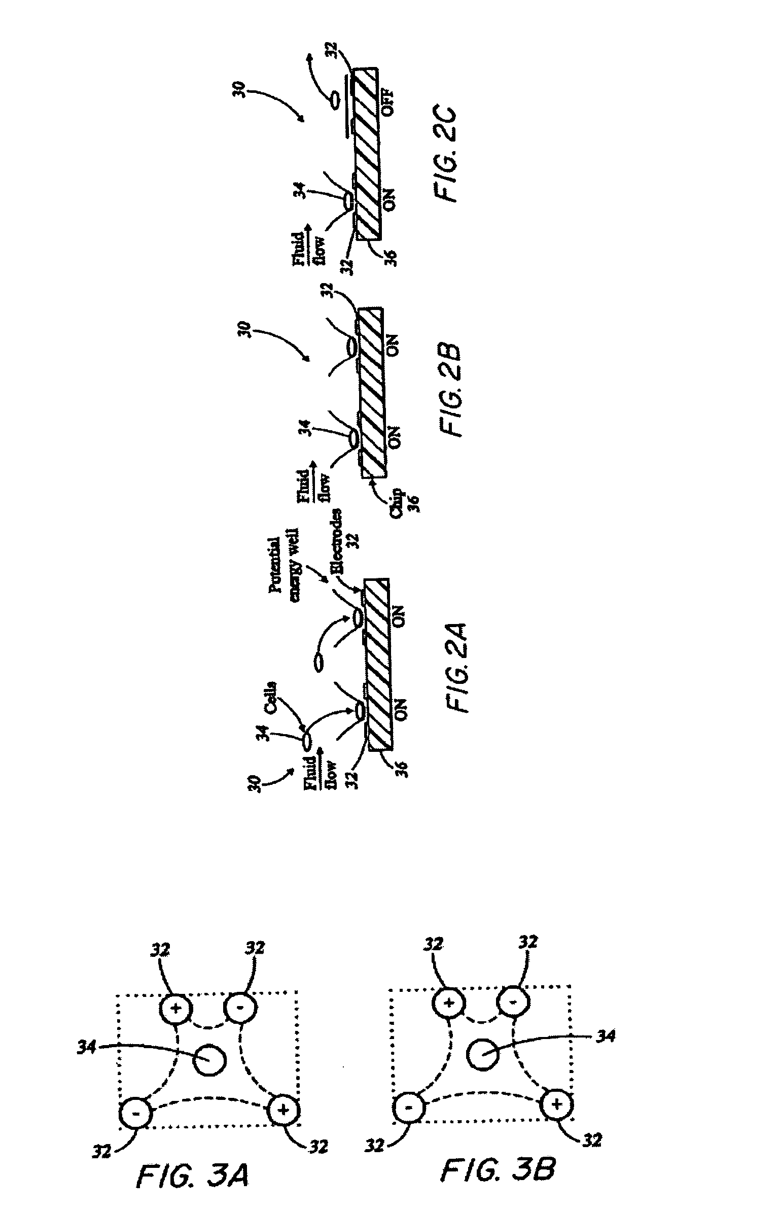
[0016] The single cell or other particulate can be held inside the well by gravitational forces. Alternatively, the particulate can be held in the well by a pressure gradient. A particulate can be captured in the well by a pressure differential between the fluid in which the particulates are flowing and the fluid in a chamber or another stream of fluid fluidically connected to the capture site. By controlling the flow rates between the two fluid flows, the pressure drop that is created can capture a particulate.

Problems solved by technology

As a fluid of cells is flown across the array of specifically sized wells, cells will fall into or be drawn into the wells and become trapped.

Method used


Image

  • Hydrodynamic capture and release mechanisms for particle manipulation
  • Hydrodynamic capture and release mechanisms for particle manipulation
  • Hydrodynamic capture and release mechanisms for particle manipulation

Examples


Embodiment Construction

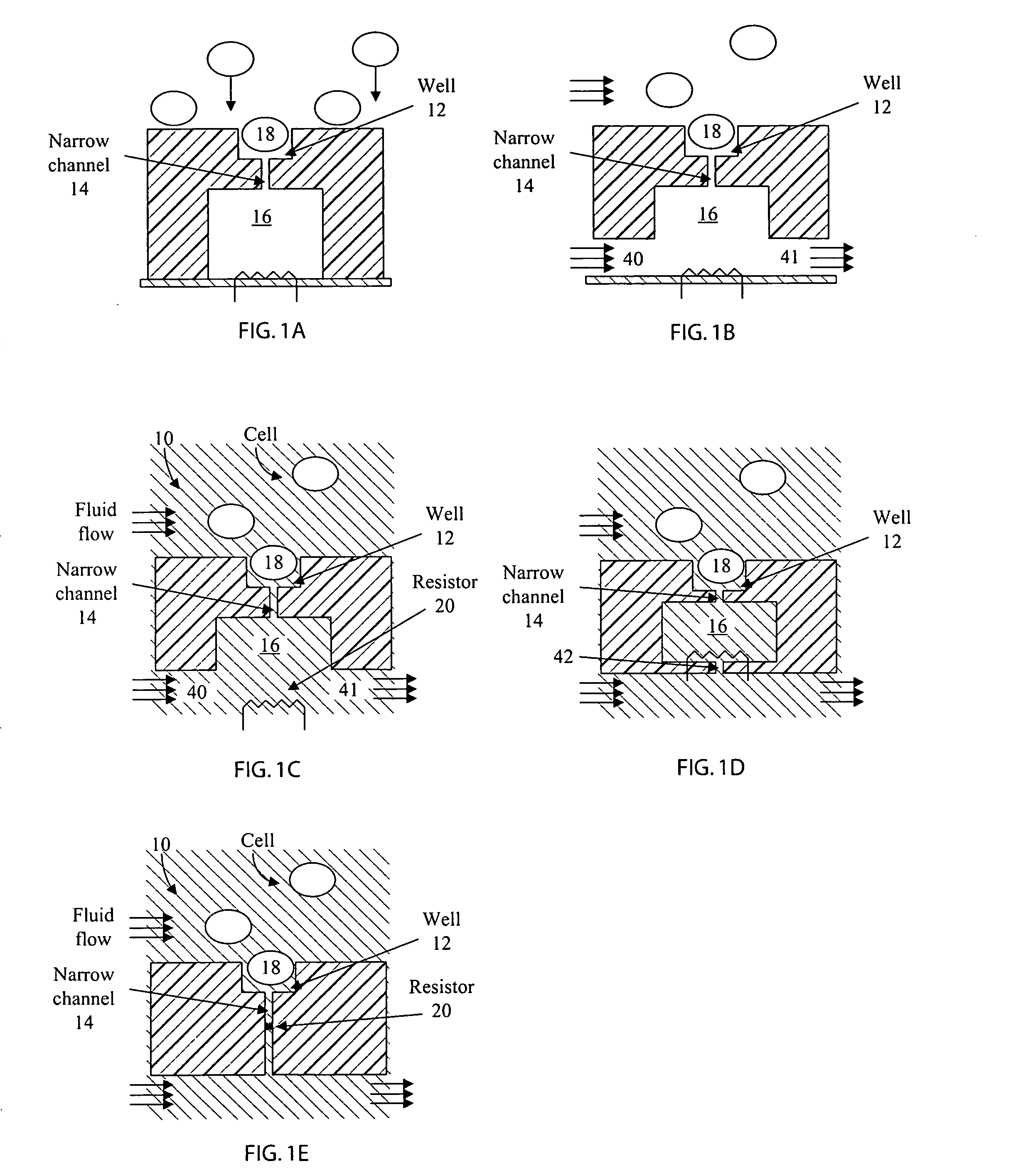
[0048]FIGS. 1A-1E illustrate exemplary capture mechanisms according to the present invention. In FIG. 1A, a particulate site 10, shown in cross-section, contains a well 12 that is sized and shaped to hold a single particulate 18. Connected to the bottom of the well 12 is a narrow channel 14 that opens into a chamber 16 situated below the well. In this particular example, the well 12 and narrow channel 14 are etched out of a silicon wafer or casted from a material such as polydimethylsiloxane (PDMS). The silicon wafer or cast is attached to a glass slide on which there is a heater 20, and the alignment is such that the heater 20 is sealed inside the chamber 16, which is filled with a fluid such as water or cellular medium.

[0049] The well 12 functions as a capture and hold mechanism to trap a single particulate. In the embodiment of FIG. 1 A, gravity is utilized as the capture mechanism to trap the particulate in well 12. In operation, fluid containing particulates are flown over the...


PUM


Abstract

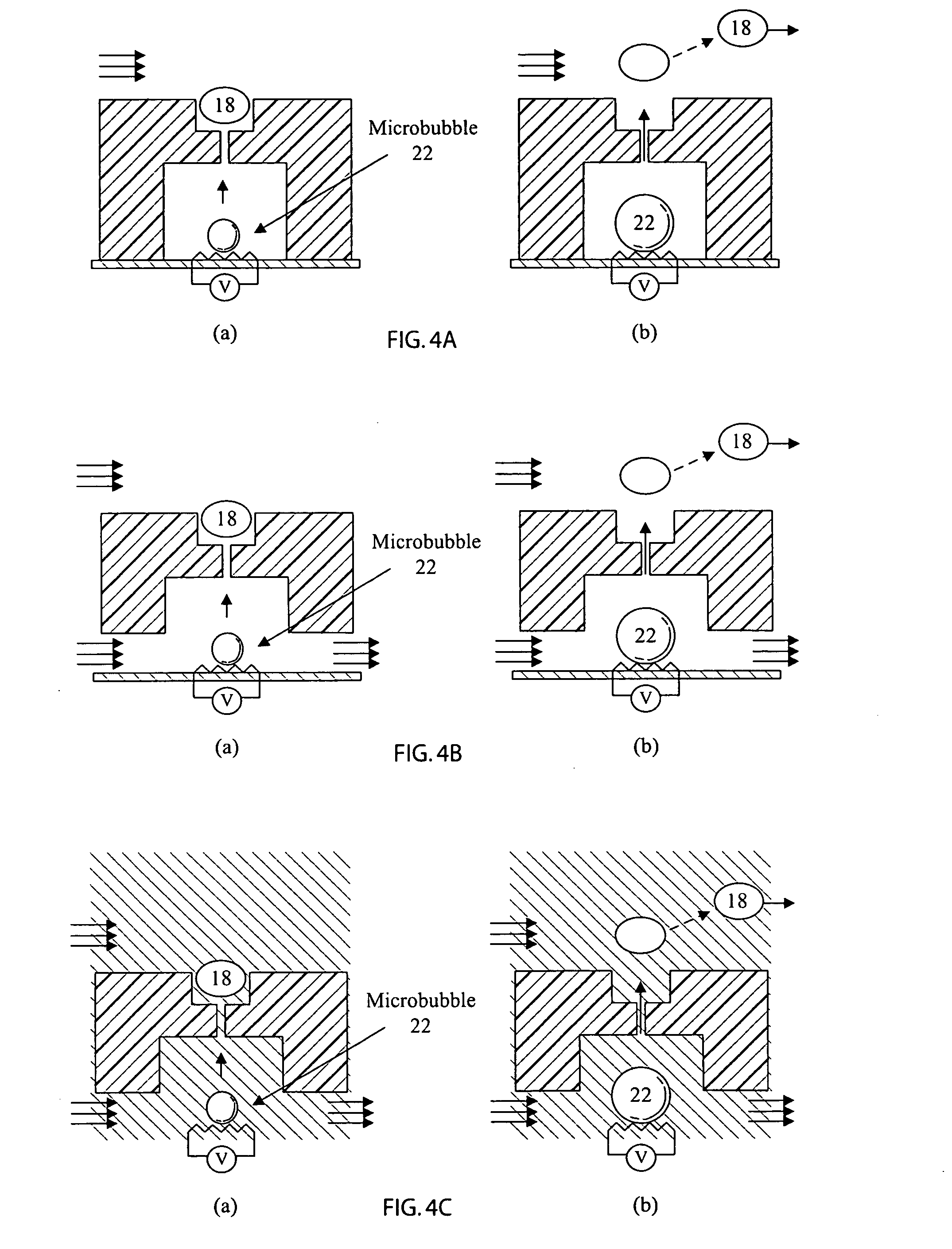
A cell analysis and sorting apparatus is capable of monitoring over time the behavior of each cell in a large population of cells. The cell analysis and sorting apparatus contains individually addressable cell locations. Each location is capable of capturing and holding a specified number of cells, and selectively releasing that specified number of cells from that particular location. In one aspect of the invention, the cells are captured and held in wells, and released using vapor bubbles as a means of cell actuation. Disclosed are: a cell manipulation apparatus design; various resistive heater configurations for nucleating microbubbles; various well designs, each in communication with a nucleation chamber or channel, for capturing a specified number of cells; and methods of fabrication and cell population manipulation.

Description

CROSS-REFERENCE TO RELATED APPLICATIONS [0001] This application is a continuation-in-part of U.S. patent application Ser. No. 10 / 778,831, filed on Feb. 13, 2004, which is a continuation of U.S. patent application Ser. No. 09 / 710,032, filed on Nov. 10, 2000, now U.S. Pat. No. 6,692,952, which claims priority to U.S. Provisional Application No. 60 / 164,643, filed on Nov. 10, 1999, each of which is incorporated herein in their entirety by reference.FIELD OF THE INVENTION [0002] This invention relates to particulate analysis and sorting devices and methods for manipulating particulates including, for example, living cells. More particularly, the invention relates to particulate analytical and sorting systems that can capture and hold individual particulates or set numbers of particulates at known locations and then selectively release certain of these particulates. Methods of manipulating the particulates via microfluidic control are also disclosed. BACKGROUND OF THE INVENTION [0003] Man...

Claims


Application Information

Patent Timeline
IPC IPC(8): H01L21/00C12M1/34
CPCB01L3/502707B01L3/502761B01L2200/0668B01L2200/12B01L2300/0816B01L2300/0819B01L2300/0877B01L2400/0415B01L2400/0442B01L2400/0487C12M47/04G01N15/1456G01N35/08G01N2035/00158G01N2035/00237G01N2035/00574
Inventor GERHARDT, ANTIMONY L.GERHARDT, GWENDOLYN L.MAXWELL, REBECCA BRAFFVOLDMAN, JOELGRAY, MARTHASCHMIDT, MARTINTONER, MEHMET
Owner GERHARDT ANTIMONY L
Learn More