Transceiver apparatus and module

Inactive Publication Date: 2006-06-15
HITACHI MEDIA ELECTORONICS CO LTD
View PDF0 Cites 246 Cited by
  • Summary
  • Abstract
  • Description
  • Claims
  • Application Information

AI Technical Summary

Benefits of technology

[0027] The module according to the present invention is formed to include a coupler for branching an output signal of the isolator and a detector circuit for detecting a signal level of an output of the coupler, wherein a bias current in the low noise amplifier circuit is increased when an output level of the detector circuit is high, and the bias current in the low noise amplifier circuit is decreased when the output level of the detector circuit is low. As a result, the power dissipation of the transceiver apparatus is decreased.
[0028] The module according to the present invention is formed to include the duplexer, the low noise amplifier circuit, the first band pass filter, the coupler, and the detector circuit. As a result, it is possible to facilitate design and reduce the size and power dissipation of the radio frequency integrated circuit for full duplex system.
[0029] The module is formed to include a plurality of duplexers, a plurality of low noise amplifier circuits, a plurality of first band pass filters, a radio frequency integrated circuit, a plurality of second band pass filters, a plurality of couplers, and a plurality of detector circuits so as to associate with a plurality of transceiver bands. As a result, it is possible to facilitate design and reduce the size and power dissipation of the radio frequency integrated circuit for full duplex system.
[0030] In addition, a control signal for turning on a low noise amplifier circuit intended only for a corresponding band among the low noise amplifier circuits is supplied from the radio frequ

Problems solved by technology

Even if the zero IF or low IF is used, therefore, it is difficult to suppress a transmission sign

Method used


Image

  • Transceiver apparatus and module
  • Transceiver apparatus and module
  • Transceiver apparatus and module

Examples


Embodiment Construction

[0050] Hereafter, aspects of the present invention will be described.

[Aspect 1]

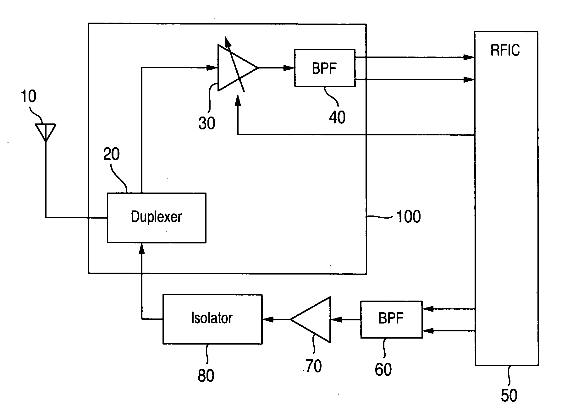
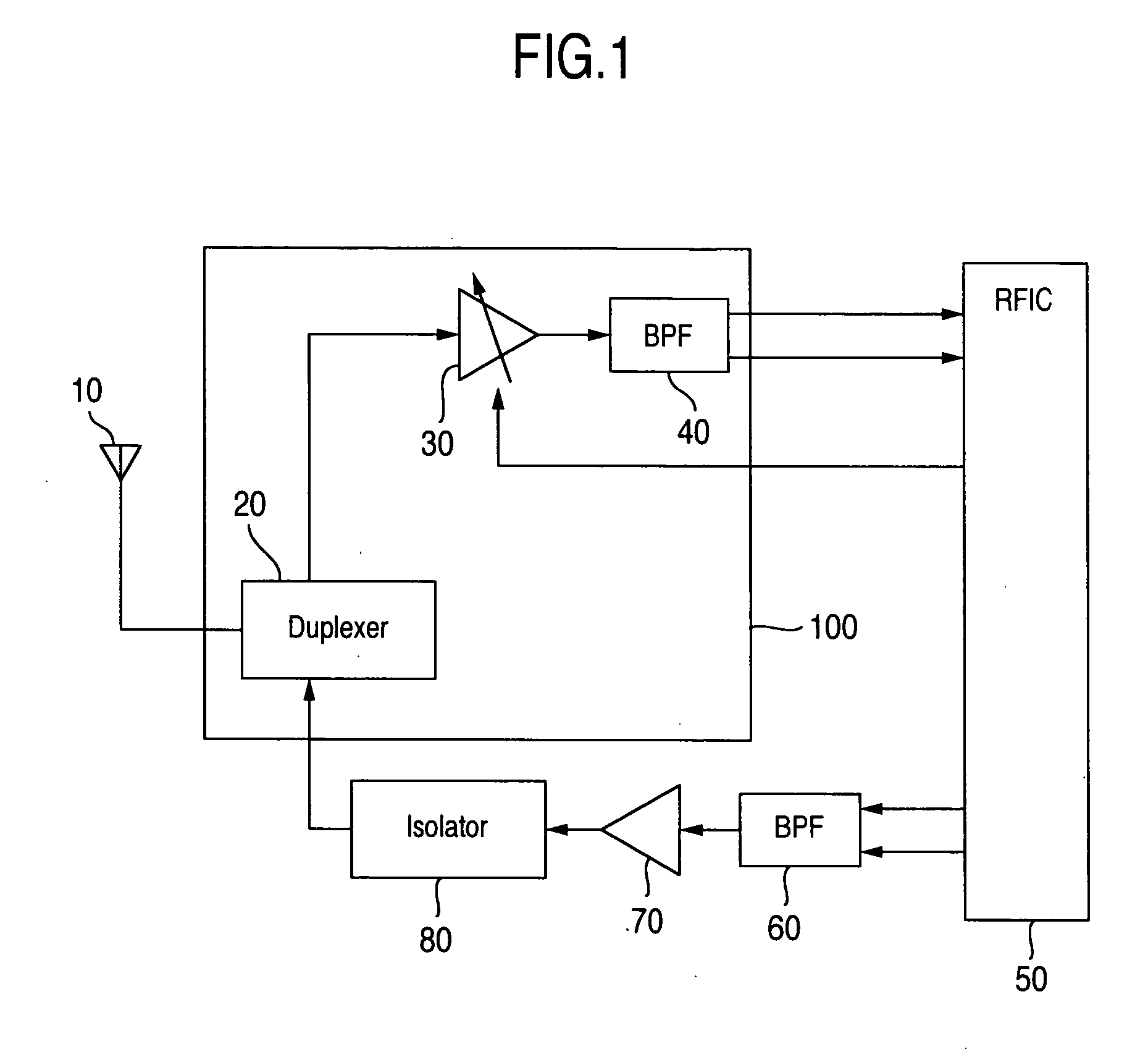
[0051]FIG. 1 is a block diagram showing Aspect 1 of a transceiver apparatus according to the present invention. In FIG. 1, reference numeral 10 denotes an antenna, 20 a duplexer, 30 an LNA, 40 a BPF, 50 an RFIC, 60 a BPF, 70 a PA, 80 an isolator, and 100 a high frequency front-end module. As for a radio frequency signal input from the antenna 10, signals in bands other than the desired band are suppressed by the duplexer 20. A resultant signal is input to the LNA 30. The LNA 30 amplifies the output signal of the duplexer 20 so as to prevent the signal-to-noise ratio (hereafter referred to as SNR) from being degraded as far as possible. An output signal of the LNA 30 is input to the BPF 40. The BPF 40 suppresses signals in bands other than the desired band, and outputs a resultant signal to the RFIC 50.

[0052] The RFIC 50 conducts processing on the radio frequency signal by using a receiver scheme such a...


PUM


Abstract

It is possible to facilitate design and reduce a size and power dissipation of a radio frequency integrated circuit RFIC for full duplex system, by forming a duplexer for passing only a desired band, a low noise amplifier circuit LNA for amplifying an output signal of the duplexer, and a BPF for passing only a desired band in an output signal of the LNA in the same module and preventing a leak level of a transmission signal to a receiver side from affecting the design of the RFIC.

Description

INCORPORATION BY REFERENCE [0001] The present application claims priority from Japanese application JP2004-357538 filed on Dec. 10, 2004, the content of which is hereby incorporated by reference into this application. BACKGROUND OF THE INVENTION [0002] The present invention relates to a transceiver apparatus. In particular, the present invention relates to components for facilitating the design and reducing the size and power dissipation of radio frequency integrated circuits for full duplex system. [0003] Conventional radio frequency circuits are formed using discrete components for each of function blocks (such as amplifiers for amplifying signals, mixers for converting signal frequencies, and filters for passing only desired bands of signals). Owing to the improvement of semiconductor techniques in recent years, it has become possible to integrate a plurality of function blocks included in the radio frequency signal circuit into one semiconductor chip (hereafter referred to as RF...

Claims


Application Information

Patent Timeline
IPC IPC(8): H04B1/44
CPCH03G3/3068H04B1/0053
Inventor IGARASHI, YUTAKAKATAGISHI, MAKOTO
Owner HITACHI MEDIA ELECTORONICS CO LTD
Why Eureka
Try Eureka