Optical transmitter suppressing excess emission of laser diode

a laser diode and optical transmitter technology, applied in the direction of laser output parameters control, semiconductor lasers, electrical apparatus, etc., can solve the problem of excessive ld emission, and achieve the effect of bias curren

Active Publication Date: 2014-05-08
SUMITOMO ELECTRIC IND LTD
View PDF3 Cites 4 Cited by
  • Summary
  • Abstract
  • Description
  • Claims
  • Application Information

AI Technical Summary

Benefits of technology

[0007]When only the second power supply is active, the bias current flowing in the LD causes a forward voltage Vf in the LD, which equivalently causes a drain bias Vds of the second transistor to generate the second bypassing current. Then, the bias current provided to the LD is decreased by the second bypassing current, by which the LD escapes from the state of the excess emission.

Problems solved by technology

However, an optical transmitter including the shunt-driver leaves a subject that, in the start of the operation, the activation of the bias current for the LD precedes the powering of the driver circuit.
Under such a situation, the driver circuit absorbs no bias current; that is a whole bias current is supplied to the LD, which results in an excess emission of the LD.

Method used


Image

  • Optical transmitter suppressing excess emission of laser diode
  • Optical transmitter suppressing excess emission of laser diode
  • Optical transmitter suppressing excess emission of laser diode

Examples


first embodiment

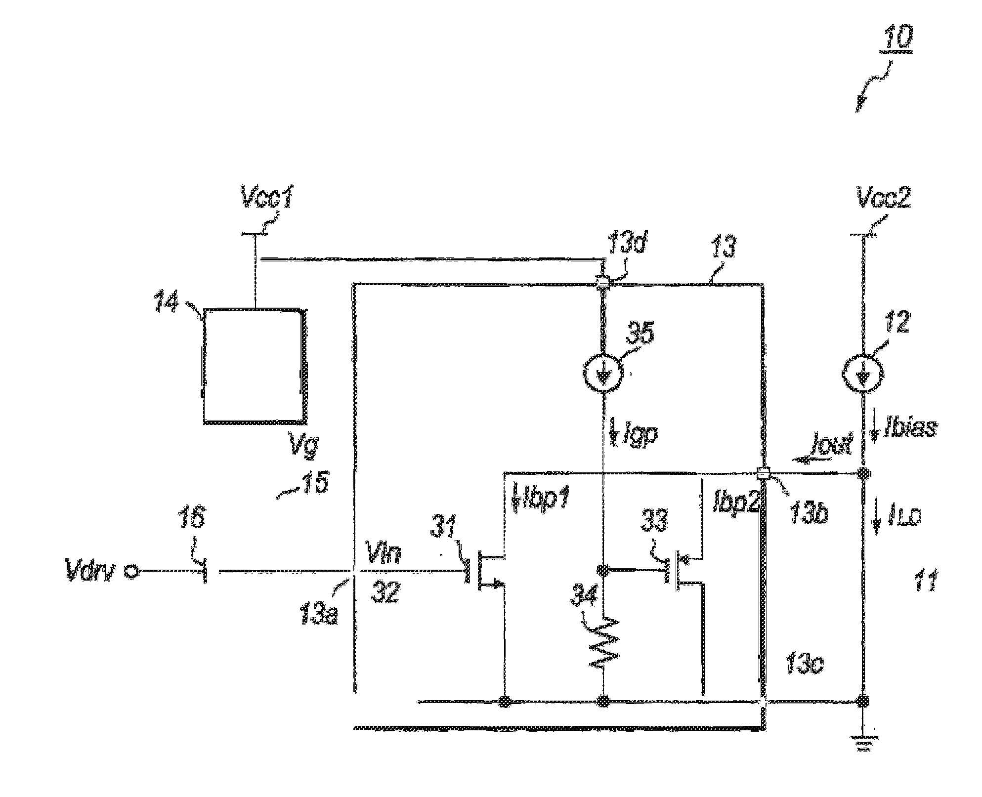
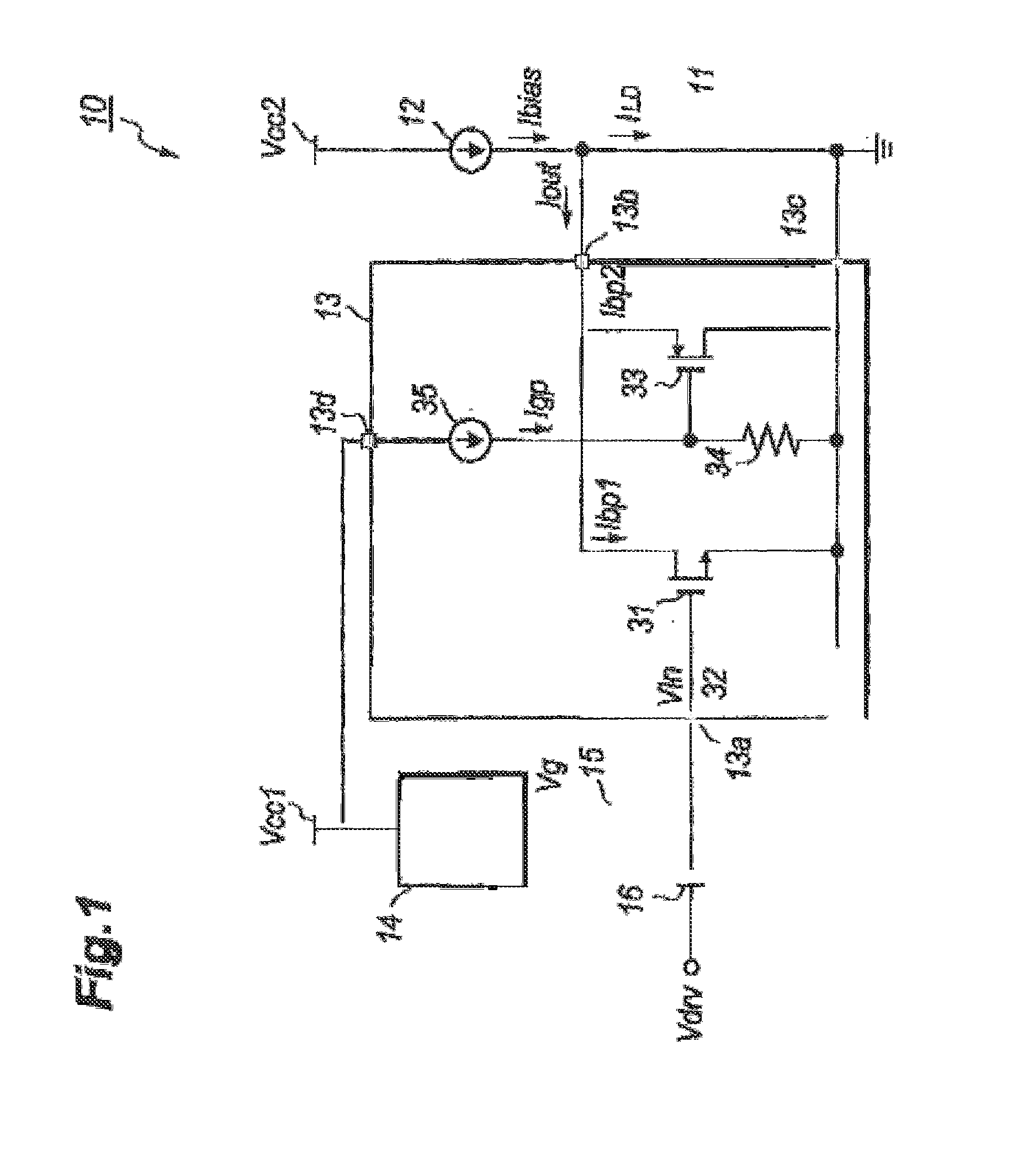
[0014]FIG. 1 shows a circuit diagram of an optical transmitter of the first embodiment. The optical transmitter 10, which is a type of what is called as the shunt-driver, primarily includes an LD 11, a first current source 12, a driver 13, a voltage source 14, an inductor 15, and a capacitor 16.

[0015]The LD 11, which is a type of semiconductor laser diode, generates an optical signal responding the driving current ILD provided thereto. An anode of the LD 11 couples with the first current source 12 and an output terminal 13b of the driver 13; while, a cathode thereof is directly connected to the ground GND. The LD 11 emits light provided with the driving current ILD derived from a bias current Ibias from the first current source 12, which generates a forward voltage Vf of about 1.3 V. The first current source 12 generates, powered by the second power supply Vcc2, the bias current Ibias to the LD 11, where the bias current Ibias is generally about 50 to 60 mA. The first current source...

second embodiment

[0039]FIG. 4 is a circuit diagram of another optical transmitter 10A having distinguishable features of providing a driver 13A modified from the aforementioned driver 13 and an inductor 17 connected in series to the LD 11.

[0040]The inductor 17 is put between the first current source 12 and the LD 11; while, the modified driver 13A provides a current terminal 13e. That is, the driver 13A provides the second transistor 33 type of the p-MOSFET whose source is connected to the current terminal 13e not the output terminal 13b as that of the first embodiment. The output terminal 13b of the driver 13 is connected to the anode of the LD 11 and a downstream terminal of the inductor 17; while, the current terminal 13e is connected to an upstream terminal of the inductor 17. That is, the inductor 17 is put between the current terminal 13e and the output terminal 13b of the driver 13.

[0041]The operation of the optical transmitter 10A is the same with that of the aforementioned optical transmitt...


PUM


Abstract

A laser diode (LD) driver to suppress the excess emission of an LD is disclosed. The LD driver has the shunt configuration with a driving transistor connected in parallel to the LD to shunt the bias current provided to the LD. The driver further provides a protection circuit to divide the bias current when the bias current is active but the driving transistor is turned off at an instant of the power on and off of the LD driver.

Description

BACKGROUND OF THE INVENTION[0001]1. Field of the Invention[0002]The present application relates to an optical transmitter, in particular, the application relates to a circuit for driving a semiconductor laser diode (hereafter denoted as LD).[0003]2. Related Background Art[0004]One type of drivers for an LD has been known as, what is called, a shunt-driver. Various prior arts have disclosed the shunt-driver circuits. The shunt-driver absorbs a primary portion of the bias current supplied to the LD responding to a driving signal provided to an input of the driver. Thus, the bias current flowing in an LD connected to the output of the shunt-driver in a primary portion thereof is shunted to the driver as leaving a rest portion in the LD. Thus, the LD is modulated by the driving signal. In order to adjust average power and an extinction ratio of an optical output of the LD, the driver often controls an input bias level thereof.[0005]However, an optical transmitter including the shunt-dri...

Claims


Application Information

Patent Timeline
Patent Type & Authority Applications(United States)
IPC IPC(8): H01S5/06
CPCH01S5/06H01S5/0427H01S5/068
Inventor MOTO, AKIHIRO
Owner SUMITOMO ELECTRIC IND LTD
Why Eureka
Try Eureka