

Driver circuit with low power termination mode
a technology of low power termination and driver circuit, which is applied in the direction of pulse generator, pulse manipulation, pulse technique, etc., can solve the problems of excessive power consumption, reduce the power needed for high speed operation, and reduce the slew current in the output stage, etc.
- Summary
- Abstract
- Description
- Claims
- Application Information
AI Technical Summary
Benefits of technology
Problems solved by technology
Method used
Image

Examples
Embodiment Construction
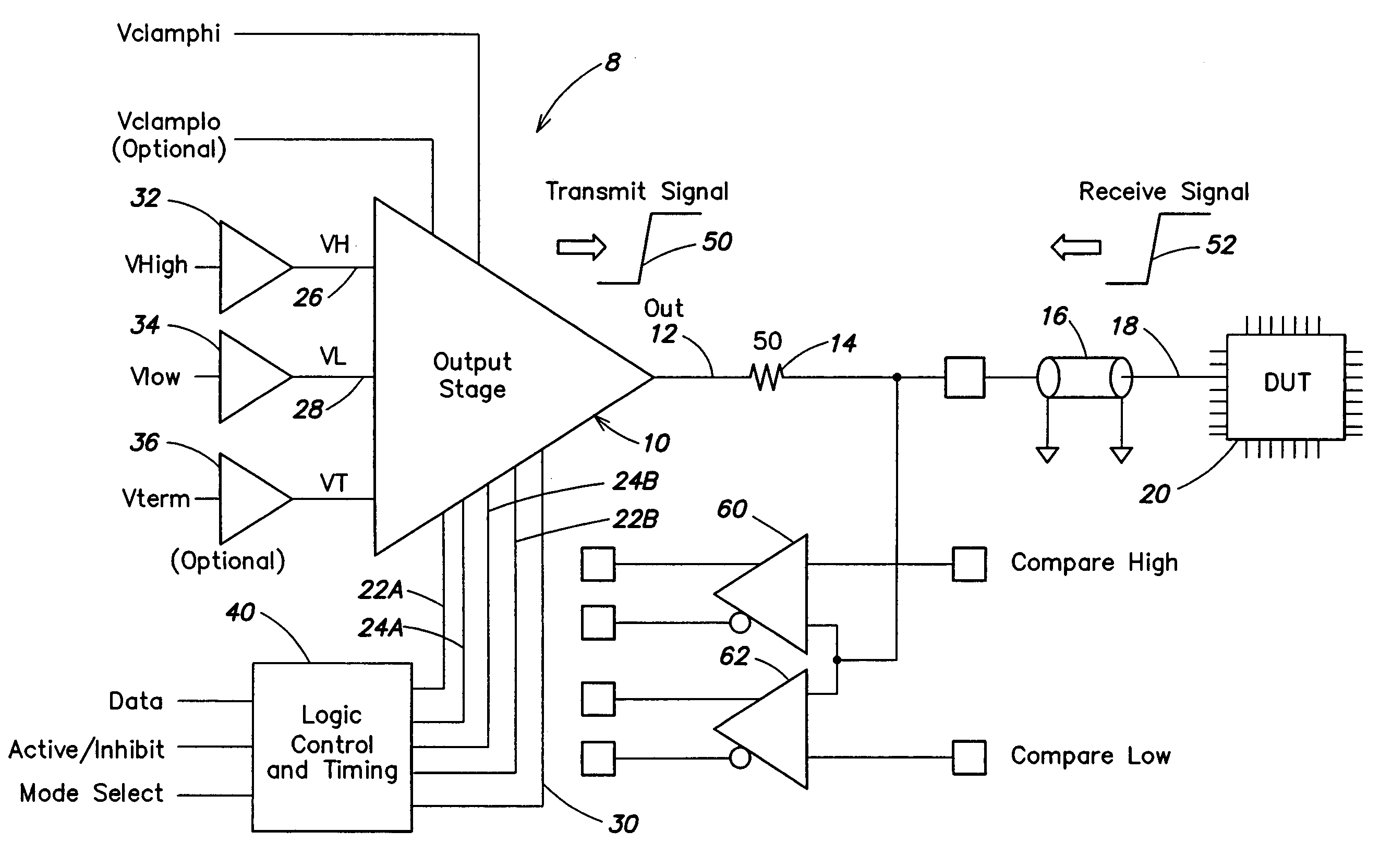
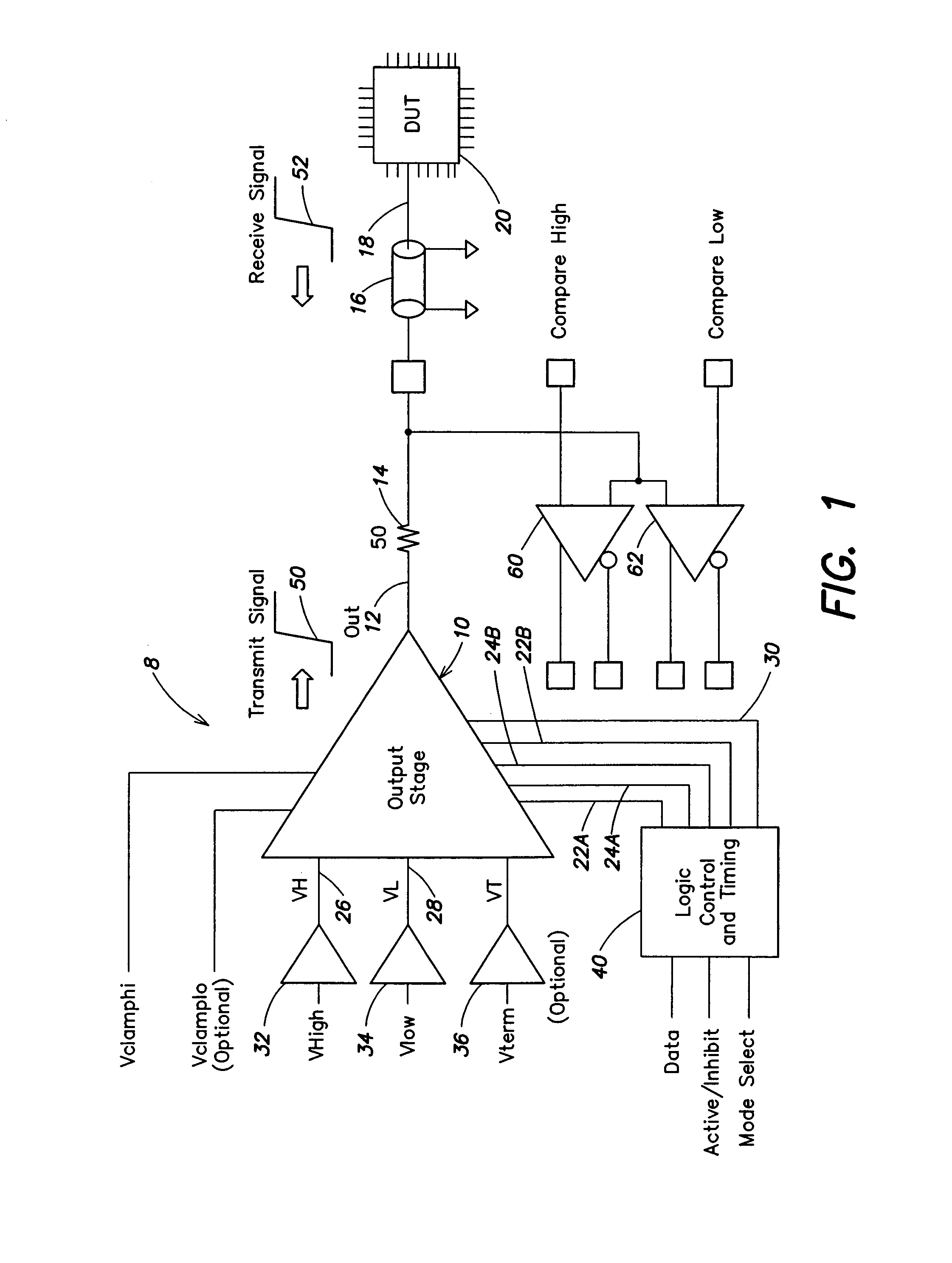
[0016]A block diagram of a pin driver circuit 8 in accordance with an embodiment of the invention is shown in FIG. 1. An output stage 10 has an output 12 coupled through a resistor 14 and a transmission line 16 to a pin 18 of a device under test (DUT) 20. Programming voltages vhigh, vlow and vterm are supplied through input buffers 32, 34 and 36, respectively, to output stage 10. The vterm level is optional and may not be utilized in some cases. Output stage 10 preferably has an inhibit state in which output 12 has high impedance and is not switched. A logic control and timing unit 40 supplies digital control signals to output stage 10, as described below. Optional Vclamphi and Vclamplo inputs may control a clamping function as described in detail in U.S. Pat. No. 6,507,231, issued Jan. 14, 2003 to Hecht et al., which is hereby incorporated herein by reference.
[0017]The logic control and timing unit 40 receives a data input, an active / inhibit input and a mode select input from a tes...
PUM
 Abstract
Description
Claims
Application Information