Method of managing user key for broadcast encryption

a technology of user key and broadcast encryption, applied in the field of broadcast encryption, can solve the problems of reduced transmission overhead, inability to use practicably, and disadvantageous efficiency of sd method, and achieve the effect of reducing transmission overhead

Active Publication Date: 2006-06-15
SAMSUNG ELECTRONICS CO LTD
View PDF5 Cites 33 Cited by
  • Summary
  • Abstract
  • Description
  • Claims
  • Application Information

AI Technical Summary

Benefits of technology

[0035] Yet another aspect of the present invention is to provide a method of managing a user key for a broadcast encrypti

Problems solved by technology

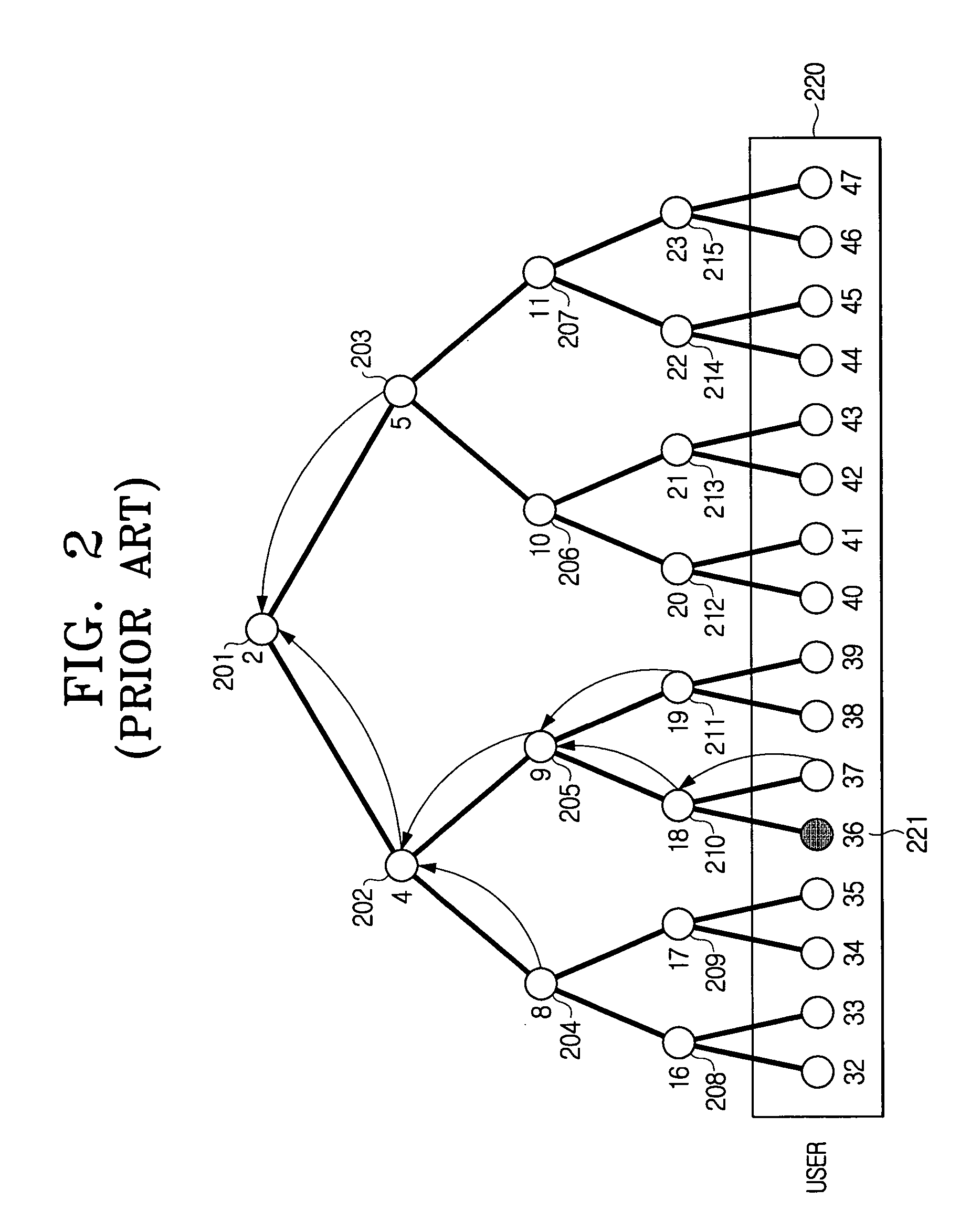
Meanwhile, another main issue of BE is to minimize transmission overhead, storage overhead and computation overhead, which means the length of headers to be transmitted by a sender, the size of user keys and the computing time of computations for a user to obtain a session key, respectively.
Among them, in particular, the most important issue is to reduce the transmission overhead.
As schemes in which the transmission overhead is proportional to r have been developed, it became an important issue to reduce the transmission overhead down to less than r.
However, the SD method also is disadvantageous in efficiency when there are a number of users.
Then, since the t privileged users know one more point (their own secret key) other than the (t+j) points, they can obtain the t+j+1 degree of polynomial P and also decrypt the secret information S. However, the revoked users know only (t+j) points, so that they can not obtain the polynomial P.
However, this method has also a disadvantage that it cannot be practically used since it is not efficient for a large group of users and security becomes weaker after the method is repeatedly used many times. A threshold secret sharing scheme using the Lagrange's interpolation formula is used in schemes proposed in a paper entitled “Efficient Trace and Revoke Schemes” by M. Noar and B. Pinkas. The schemes proposed by Noar-Pinkas use an idea that a polygonal expression of (r+1) degree can be recovered using (r+1) points on the polynomial of (r+1) degree but cannot be recovered with r points that lack one point to recover the polynomial of (r+1) de

Method used


Image

  • Method of managing user key for broadcast encryption
  • Method of managing user key for broadcast encryption
  • Method of managing user key for broadcast encryption

Examples


first modified exemplary embodiment

[0122] In the basic exemplary embodiment described above, the transmission overhead is greater than r because the length of an interval is limited to c. Accordingly, to reduce the transmission overhead to as much as r, the first modified exemplary embodiment, which transmit the keys by one transmission to a longer interval than c is proposed.

[0123] In the first modified exemplary embodiment of the present invention, special nodes are set in a certain interval, for example, for every 3-th node. Then, special seed value keys randomly selected and different from the existing seed value keys are assigned to the respective special nodes, and a special node chain starting from one special node key is constructed.

[0124]FIG. 12 is a view showing definition of the special nodes in the straight line structure in accordance with the first modified exemplary embodiment of the present invention. Referring to FIG. 12, the special nodes 1201, 1202 and 1203 are set for every c-th node. The specia...

second modified exemplary embodiment

[0136] According to the first modified exemplary embodiment, it is possible to obtain the transmission overhead which is approximately the same as r. That method shows the best result in the transmission overhead among the currently known methods such as the SD method with the transmission overhead of 2r−1. A second modified exemplary embodiment to be described hereinafter can reduce the transmission overhead to as much as less than r.

[0137] The basic concept of the second modified exemplary embodiment is as follows. In a case that a set of users positioned between two revoked users is regarded as an interval, the total number of intervals can never be below r in the worse case. In such cases, since one transmission should be made for each interval, it is impossible that the transmission overhead becomes less than r. Thus, it is necessary to alter a method of defining an interval.

[0138] Accordingly, a transmission interval can be set by including more than one revoked user in the ...

third modified exemplary embodiment

[0151] A third modified exemplary embodiment of the present invention is derived by combining the first and second modified exemplary embodiments. In this case, it is the worst case when every interval having a length c includes one revoked user. In a case that an interval having the length less than c includes two or more revoked users, the transmission for the two revoked users can be carried out at a time by using the second modified described above. The transmission overhead and storage overhead in such worst case are r / 2+(N−2r) / 2(c−2) and c+c2+(c−1)(c−2) / 2, respectively.

[0152] The transmission overhead r / 2+(N−2r) / 2(c−2) can be applied to the case that r is greater than N / c. If r is smaller than N / c, different results are obtained. For example, assuming that r equals zero, the transmission overhead becomes N / (c×c2). At this time, as r gradually increases, the transmission is needed once for the interval including the revoked users and having the length c. Further, since the met...


PUM


Abstract

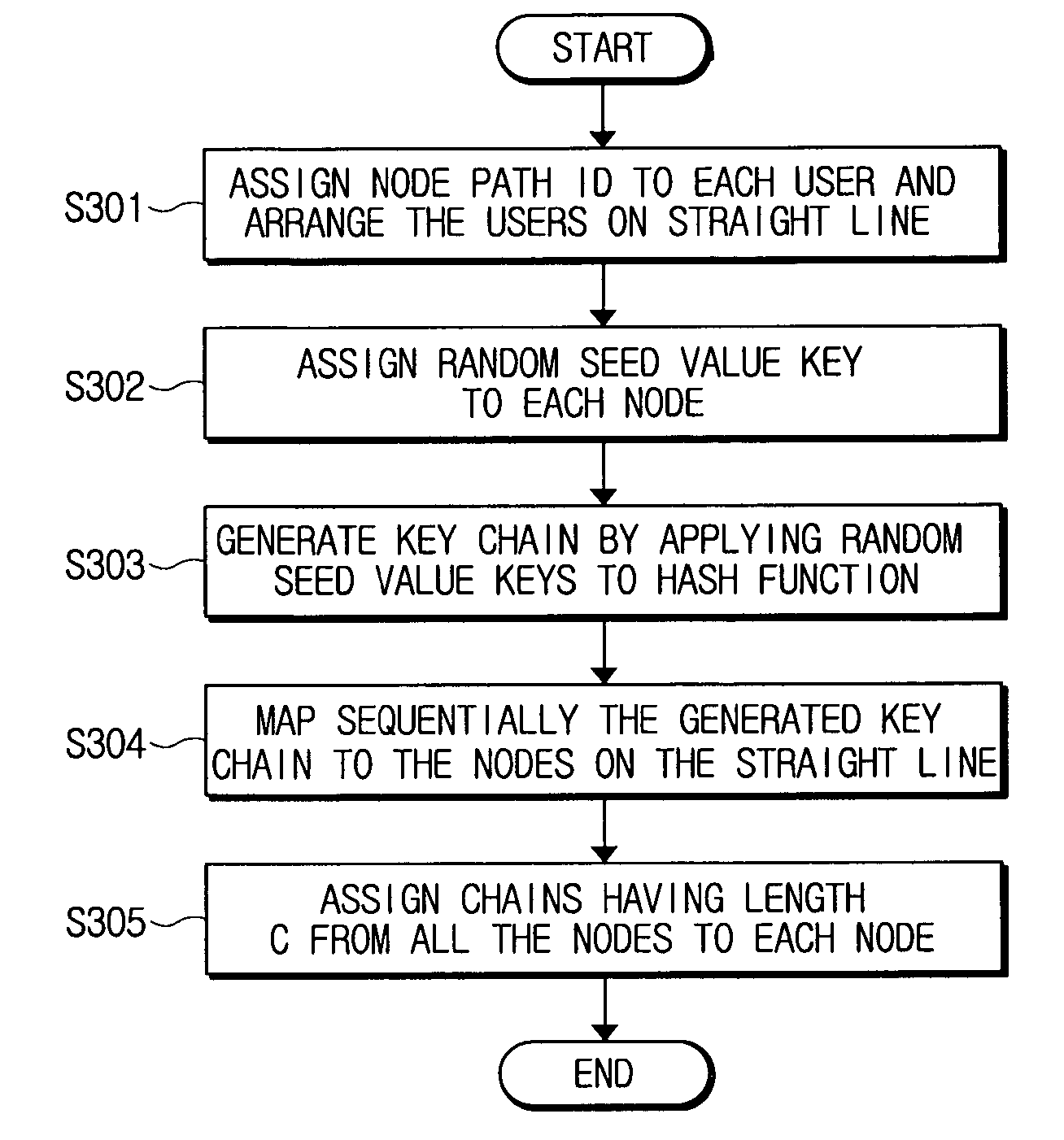
A user key management method for a broadcast encryption includes assigning node path identifiers (IDs) to nodes arranged in sequence; assigning random seed value keys to the nodes according to the node path IDs; generating key values by repeatedly applying a hash function to the assigned random seed value keys; and assigning the generated key values to the nodes in sequence. Accordingly, it is possible to reduce the transmission overhead that is most important matter in the broadcast encryption to less than the number of the revoked users. Further, there is an advantage that the transmission overhead of the exemplary embodiments of the present invention is remarkably reduced compared with the Subset Difference method.

Description

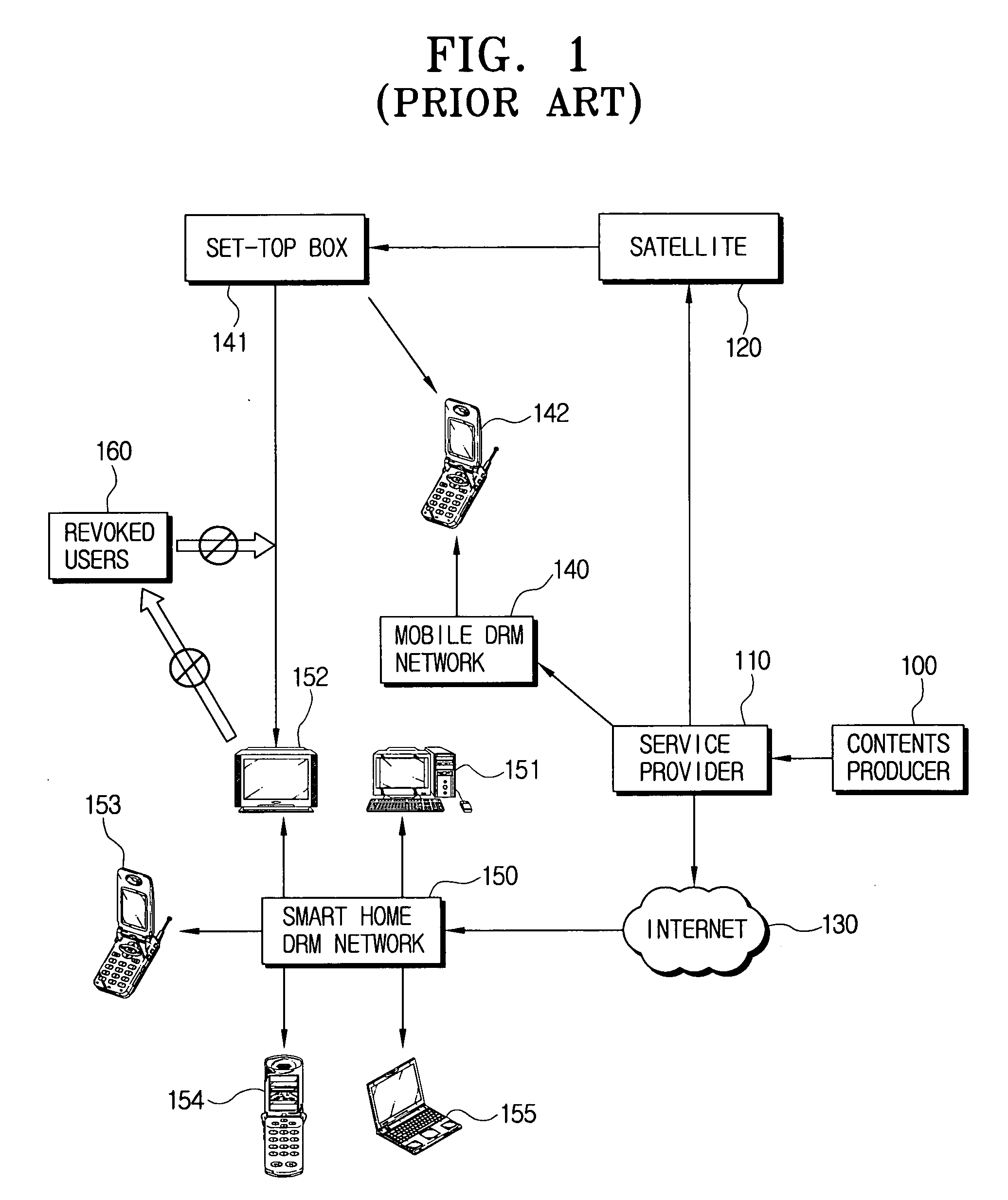
[0001] This application claims priority from Korean Patent Application Nos. 2004-92431, 2005-106604 and 2005-100726, filed on Nov. 12, 2004, November 8, 2005 and Oct. 25, 2005, respectively, the entire content of which is incorporated herein by reference. BACKGROUND OF THE INVENTION [0002] 1. Field of the Invention [0003] Methods consistent with the present invention relate to broadcast encryption, and more specifically, to managing a user key for a broadcast encryption. [0004] 2. Description of the Related Art [0005] Broadcast encryption (BE) is used for a sender (that is, a broadcast center) to efficiently transmit information to only intended users among all users. This scheme should be effectively used when a set of users receiving the information changes randomly and dynamically. In BE, the most important issue is to revoke or exclude disapproved users (for example, revoked users or expired users). [0006]FIG. 1 is a conceptual view showing a network construction of a data trans...

Claims


Application Information

Patent Timeline
IPC IPC(8): H04L9/00G06F15/00H04N21/2347H04L9/08H04L9/32H04N21/6334
CPCH04L9/0822H04L9/0827H04L9/0836H04L9/0869H04L9/0891H04L2209/38H04L2209/601H04N7/162H04N7/1675H04N21/2585H04N21/26613H04L2209/606H04N21/222H04L9/50H04N21/2347H04N21/6334H04L9/32G06F15/00
Inventor KIM, DAE-YOUBJIN, WEON-ILKIM, HWAN-JOONPARK, SUNG-JOONCHEON, JUNG-HEEKIM, MYUNG-HWANJHO, NAM-SUYOO, EUN-SUN
Owner SAMSUNG ELECTRONICS CO LTD
Why Eureka
Try Eureka