
Magnetic disk drive manufacturing method, test/adjustment apparatus, and transport container

a magnetic disk drive and manufacturing method technology, applied in the direction of magnetic recording, recording head protective measures, record carrier construction details, etc., can solve the problems of increased investment in testing apparatus and time required for the execution of test/adjustment procedures, and defective magnetic disk drives

Inactive Publication Date: 2006-06-22
HITACHI GLOBAL STORAGE TECH NETHERLANDS BV
View PDF11 Cites 62 Cited by
  • Summary
  • Abstract
  • Description
  • Claims
  • Application Information

AI Technical Summary

Benefits of technology

[0006] The applicant of the present invention previously filed an application, Japanese Patent Application No. 2004-78569, disclosing a technology for using a magnetic disk drive, which has gone through with an optimization / inspection process, as a testing apparatus by operating it in a host mode to transfer files to another magnetic disk drive and perform tests. The applicant of the present invention also filed an application, Japanese Patent Application No. 2004-200347, disclosing a technology concerning a test controller, which permits a magnetic disk drive under test to locally perform test / adjustment procedures without being limited by the size and characteristics of a test / adjustment program, and makes it possible to test magnetic disk drives that employ the ATA interface.
[0007] When a test / adjustment method disclosed by the above-mentioned previously filed patent applications is to be actually applied to a magnetic disk drive manufacturing process, it is necessary, for instance, to reduce the amount of investment in a testing apparatus and increase the yield rate prevailing between assembly completion and shipment. The transport container was merely used to pack finished magnetic disk drives. It is convenient, however, that the transport container be also used in the magnetic disk drive manufacturing process.
[0011] The plurality of magnetic disk drives to be subjected to the test / adjustment process are held by the shock absorber so that the interface connectors are exposed. Therefore, it is possible to connect all the testing side connectors, which are mounted on a base plate, to the interface connectors, send the test / adjustment program, and have the magnetic disk drives execute the test / adjustment program. Since the magnetic disk drives are held by the shock absorber, they do not bump against something, drop, or become damaged during the test / adjustment process. Further, the productivity increases because a plurality of magnetic disk drives may be simultaneously handled.
[0012] The test / adjustment program includes, for instance, a program for writing servo information into a magnetic disk drive by a self servo write method and a command test, which is performed relative to the host apparatus. When a magnetic disk drive that is capable of operating in a host mode is employed as the host apparatus, it is not necessary to use a testing computer, thereby reducing the amount of investment in the test / adjustment process. When an RFID tag is attached to the shock absorber, it is possible to cover a plurality of magnetic disk drives with one tag and gather dynamic information about errors encountered in the test / adjustment process and the progress of the process for management purposes.
[0013] When the test / adjustment process is performed while the shock absorber and the magnetic disk drives held by the shock absorber are positioned in a shipment transport box, there is no need to use a chamber or other storage facilities for the test / adjustment process. It is also possible to simplify a magnetic disk drive transport operation that is to be performed in a factory.

Problems solved by technology

However, when the magnetic disk drives were to be mass-produced, the use of the above method increased the amount of investment in the testing apparatus and the time required for the execution of the test / adjustment procedures.
In addition, some magnetic disk drives became defective when they bumped against something or dropped during transit.

Method used


Image

  • Magnetic disk drive manufacturing method, test/adjustment apparatus, and transport container
  • Magnetic disk drive manufacturing method, test/adjustment apparatus, and transport container
  • Magnetic disk drive manufacturing method, test/adjustment apparatus, and transport container

Examples


Embodiment Construction

Description of a Method for Switching into a Host Mode and the Like

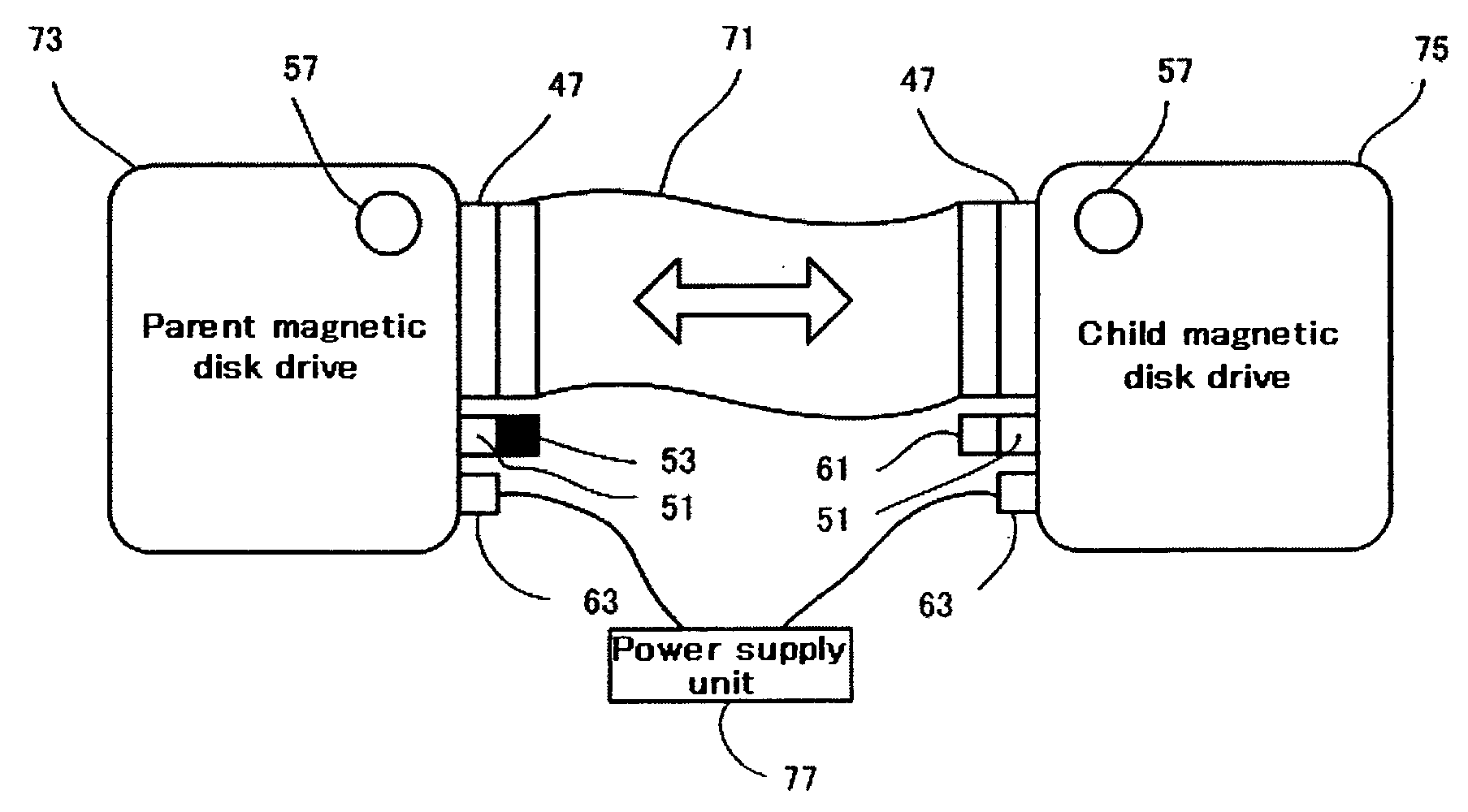
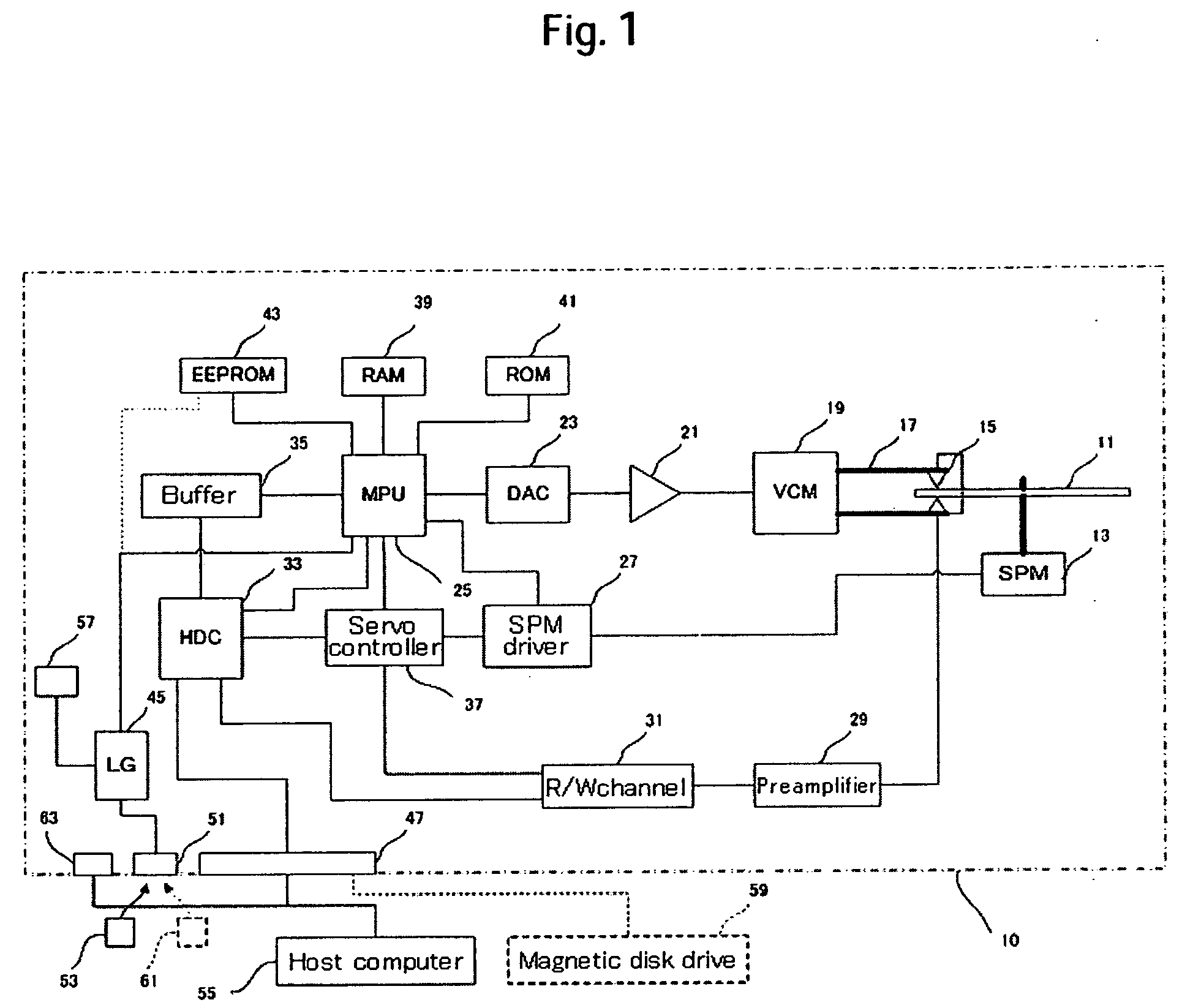
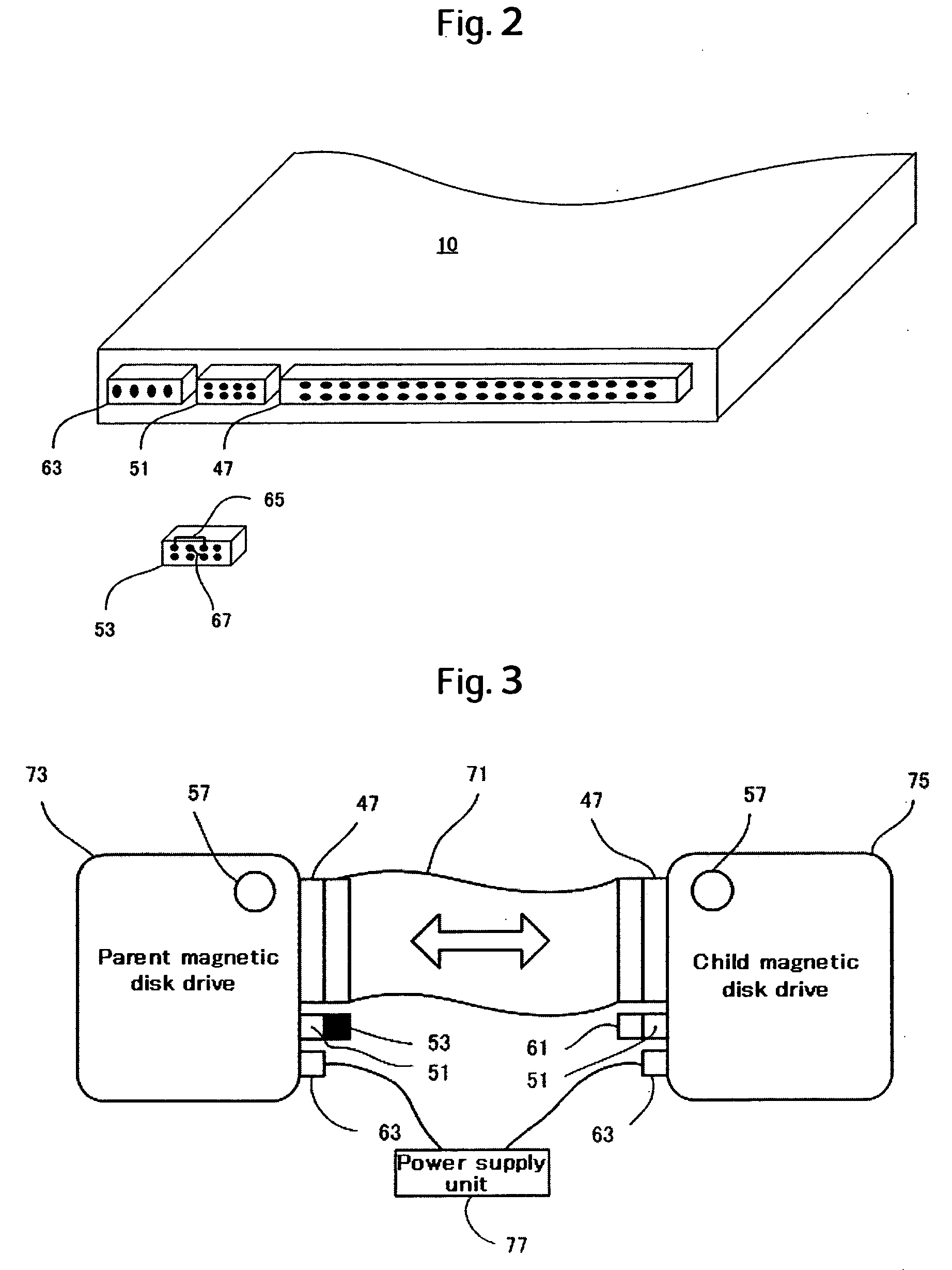
[0038] First of all, a magnetic disk drive that may safety alternate between a host mode and device mode, which were operating modes proposed by a previous patent application, and a magnetic disk drive that operates in the host mode to transfer data directly to another magnetic disk drive or perform an optimization / inspection process will be described. Within this document, the meaning of the term “optimization / inspection process” is the same as that of the test / adjustment process.

Description of a Magnetic Disk Drive

[0039]FIG. 1 is a block diagram illustrating major components of a magnetic disk drive 10. The magnetic disk drive 10 has two operation modes: host mode and device mode. In the host mode, the magnetic disk drive operates like a host computer for another magnetic disk drive. More specifically, the magnetic disk drive in the host mode actively accesses another magnetic disk drive, for instance, to perf...


PUM

PropertyMeasurementUnit
Pressureaaaaaaaaaa

Abstract

The present invention provides an improved magnetic disk drive manufacturing method that is to be employed during an interval between magnetic disk drive assembly completion and shipment. In one embodiment, a magnetic disk drive has an interface connector. The magnetic disk drive is retained by a shock absorber so that the interface connector is exposed. A testing side connector mounted on a base plate is connected to the interface connector of the magnetic disk drive that is retained by the shock absorber. A host apparatus transfers a test / adjustment program to the magnetic disk drive via the testing side connector. The magnetic disk drive executes the test / adjustment program.

Description

CROSS-REFERENCES TO RELATED APPLICATIONS [0001] This application claims priority from Japanese Patent Application No. JP2004-369029, filed Dec. 21, 2004, the entire disclosure of which is incorporated herein by reference. BACKGROUND OF THE INVENTION [0002] The present invention relates to a magnetic disk drive manufacturing method, test / adjustment apparatus, and transport container, and more particularly to a technology for simplifying a manufacturing process that is to be performed during an interval between magnetic disk drive assembly completion and shipment. [0003] The process for assembling a magnetic disk drive is performed by mounting a magnetic disk, actuator, and other component parts on a base, installing a base cover over the base, and mounting a circuit board on an enclosure, which comprises the base and base cover. During a time interval between the instant at which the magnetic disk drive hardware is completely assembled and the instant at which the magnetic disk drive...

Claims


Application Information

Patent Timeline
IPC IPC(8): G11B5/127G01N27/82B23P19/00
CPCG11B5/40G11B5/455G11B5/5582Y10T29/49025G11B33/126Y10T29/53165Y10T29/49036G11B33/12
Inventor TAKASE, MAKOTOKAI, KEIICHIROHSUGANUMA, SHIGEMINAGASAWA, HIROSHI
Owner HITACHI GLOBAL STORAGE TECH NETHERLANDS BV
Learn More