Balancing machine

Inactive Publication Date: 2006-06-22
TURNER LEGAL REPRESENTATIVE JUDITH ANN +2
View PDF29 Cites 20 Cited by
  • Summary
  • Abstract
  • Description
  • Claims
  • Application Information

AI Technical Summary

Benefits of technology

[0011] Accordingly, it is the object of this invention to provide a new and improved device whose purpose is to detect and measure rotational imbalance in mechanical components, retaining all the functions of the prior art while eliminating certain features which require increased size, weight, and cost, thereby demonstrating that a relatively small, l

Problems solved by technology

In order to achieve this, however, the machine was m

Method used


Image

  • Balancing machine
  • Balancing machine
  • Balancing machine

Examples


Embodiment Construction

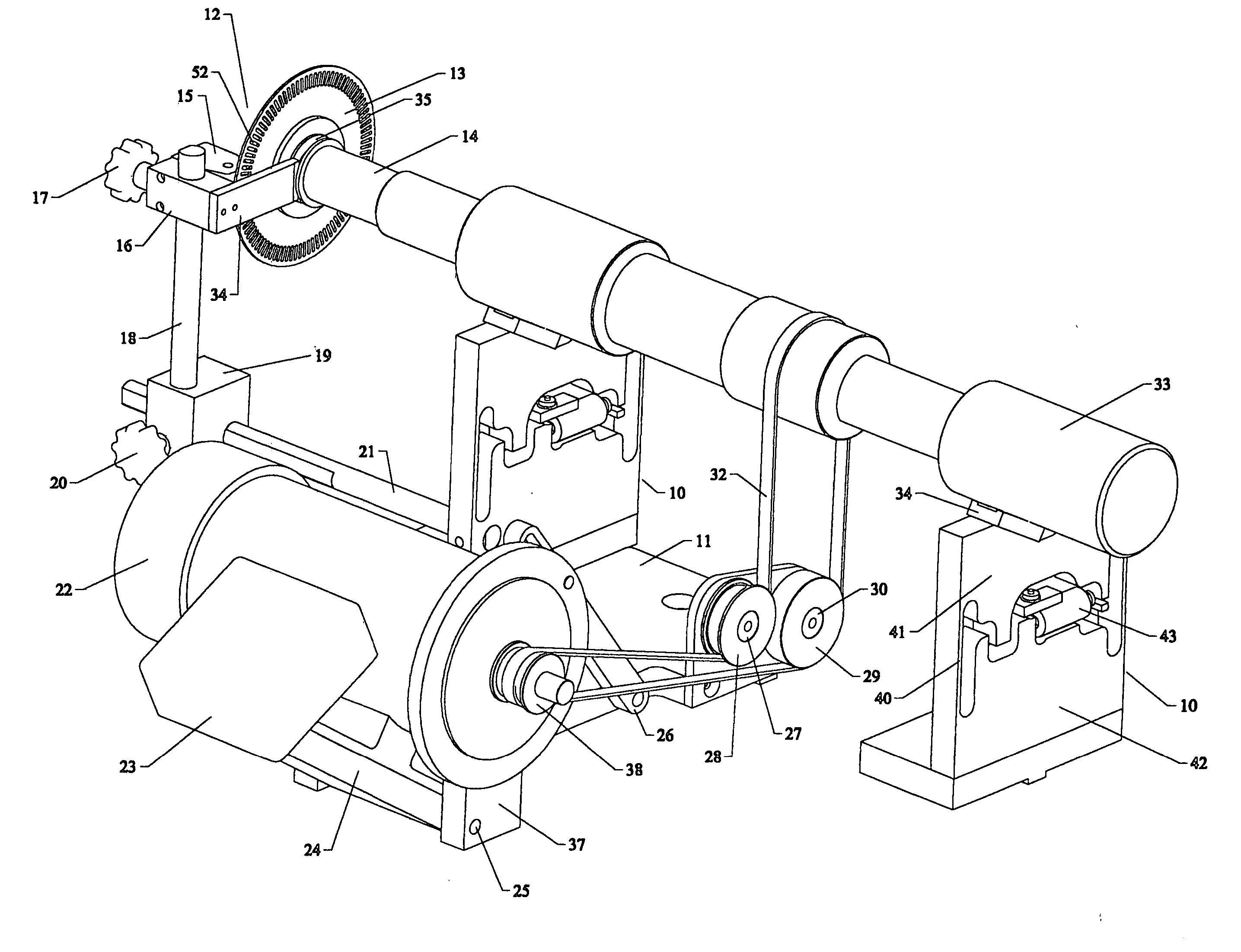
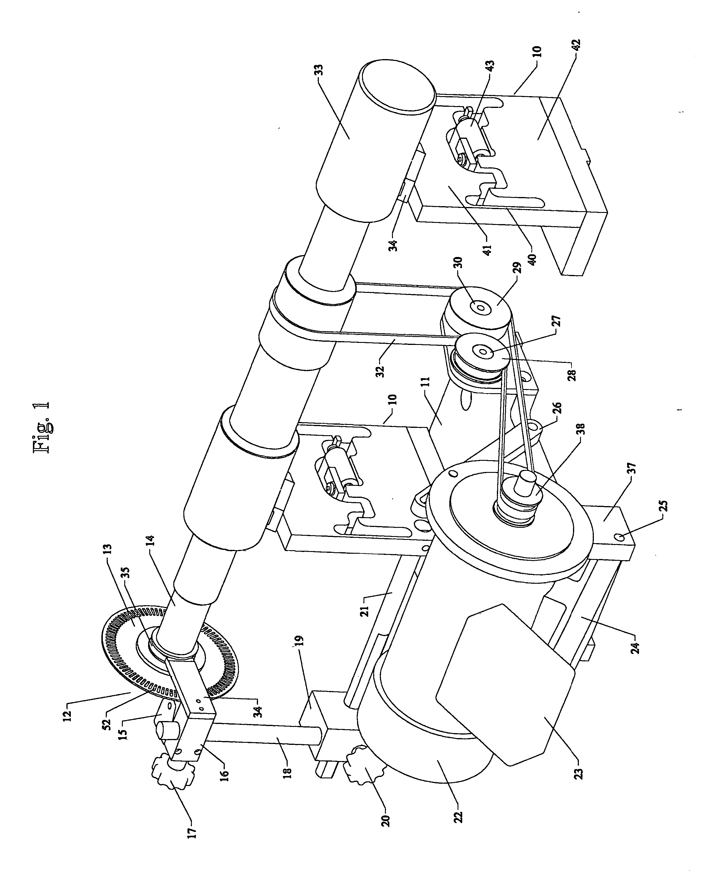
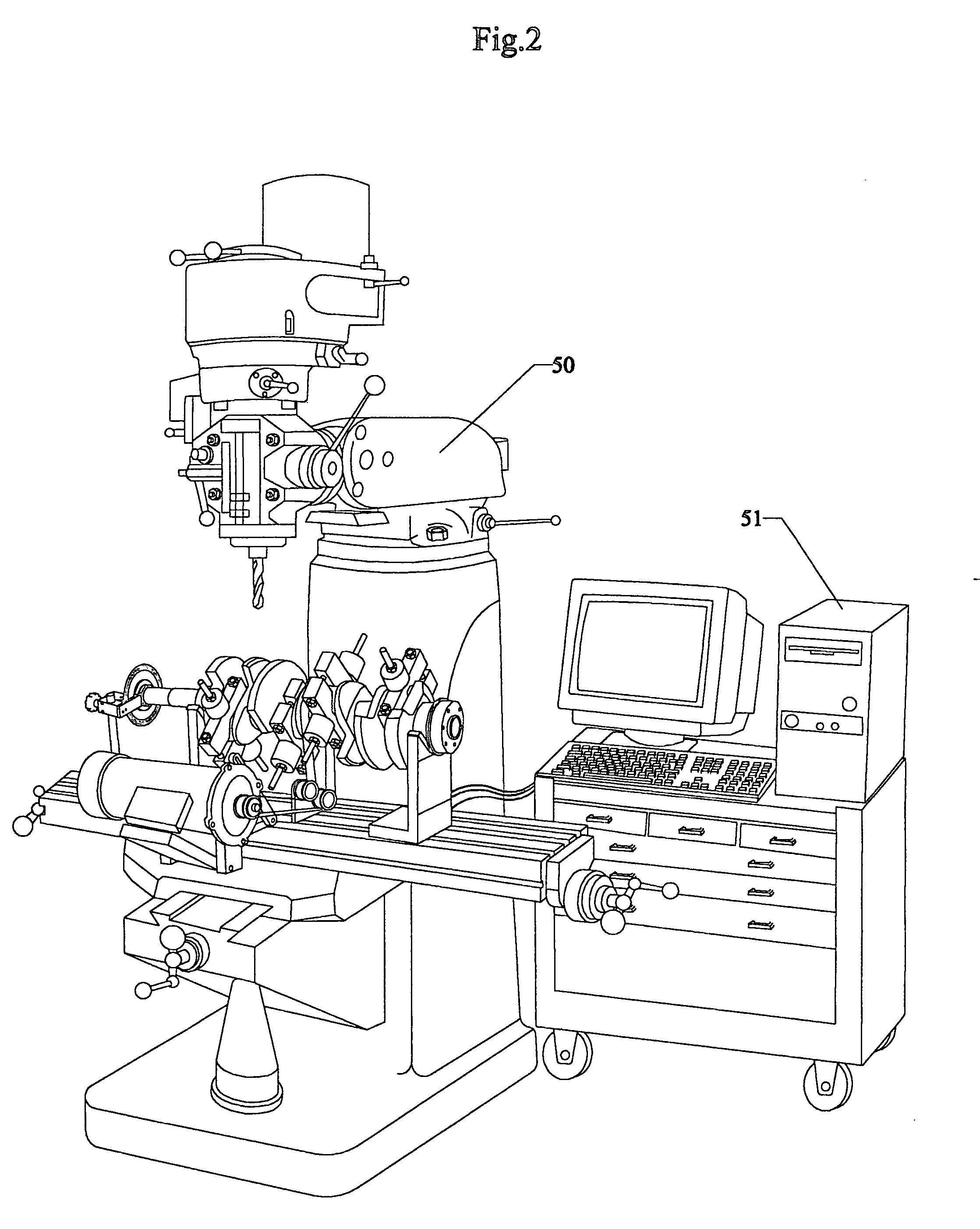
[0028] While it is to be borne in mind that this invention can be attached to different types of machine tools and configured for balancing many different mechanical components, one of the areas where it finds usefulness is in the balancing of automotive crankshafts. Many small engine shops can not afford the purchase price and the floor space required by the large units that are now commercially available. In the preferred embodiment, the invention is uniquely advantageous when configured as an attachment to a vertical milling machine of the type frequently already owned by these shops. If the purchase of a milling machine is necessary, the mill is not permanently dedicated to balancing. The balancing machine can be easily removed from the mill, leaving it fully functional for other work. It should also be noted that the combined purchase price of the milling machine and the balancing machine is less than the cost of a dedicated balancing machine as shown in FIG. 6. Accordingly, it...


PUM


Abstract

An improved and simplified balancing machine comprising upright supports devices to hold the workpiece to be balanced, a motor and mount to spin the workpiece, and a system to detect and measure imbalance in the workpiece when it is rotated at speed. Said machine configured to be attached to a machine tool or work table without losing functional integrity, thereby eliminating the need for a massive base. Specific preferred structural embodiments are disclosed.

Description

FIELD OF THE INVENTION [0001] The invention relates to a machine for detecting and measuring rotational imbalance of mechanical components. More particularly, this invention relates to an improvement in balancing machine technology through a more simplified design which eliminates the need of certain components. DESCRIPTION OF THE PRIOR ART [0002] Prior art in balancing machines consist of large free standing machines. They incorporate a massive base, support devices to hold the workpiece to be balanced, a motor mounted in said base to spin said workpiece, and a system to detect and measure imbalance in said workpiece when it is rotated at speed. One type of balancing machine requires that said workpiece be removed from the balancer in order that said workpiece be drilled, ground or otherwise brought into a dynamically balanced state. Other types of these machines are so large that a milling / drilling machine is mounted on said massive base, allowing said milling / drilling machine to ...

Claims


Application Information

Patent Timeline
IPC IPC(8): G01M1/38G01M1/34G01M1/06
CPCG01M1/24
Inventor TURNER, WILLIAM F.TURNER, WARREN K.TURNER, JUDITH ANN
Owner TURNER LEGAL REPRESENTATIVE JUDITH ANN
Why Eureka
Try Eureka