Thermoelectric generator

a generator and thermoelectric technology, applied in the field of thermoelectric generators, can solve the problems of deteriorating recovery efficiency, difficult to sufficiently maintain the temperature difference on the surface of thermoelectric elements, and deteriorating cooling performance, so as to suppress the decrease of the flow rate of cooling water, maintain the capacity of cooling an engin

Inactive Publication Date: 2006-06-22
DENSO CORP +1
View PDF5 Cites 69 Cited by
  • Summary
  • Abstract
  • Description
  • Claims
  • Application Information

AI Technical Summary

Benefits of technology

[0008] The present invention is made in view of the foregoing matter, and it is an object of the present invention to provide a thermoelectric generator capable of generating e...

Problems solved by technology

This results in deterioration of cooling performance.
However, if the coefficient of thermal conductivity is increased, it is difficult to sufficiently maintain the temperature difference on th...

Method used


Image

  • Thermoelectric generator
  • Thermoelectric generator
  • Thermoelectric generator

Examples


Embodiment Construction

[0017] Embodiments of the present invention will be described hereinafter with reference to the drawing.

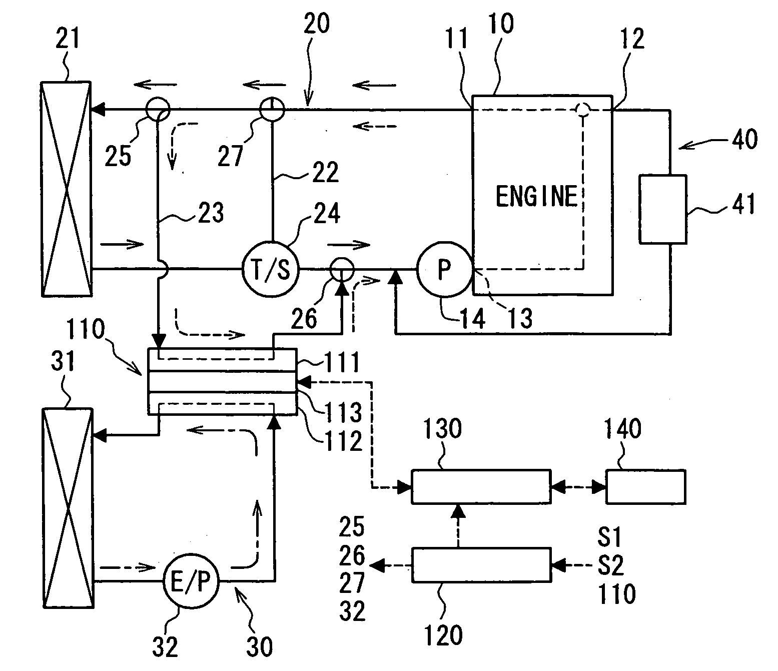
[0018] Referring to FIG. 1, a thermoelectric generator system 100 is mainly constructed of a thermoelectric generator 110 and a control device 120 for controlling operation of the thermoelectric generator 110. The thermoelectric generator system 100 is used in a vehicle having a water-cooled engine 10 for recovering electric energy from waste heat energy of the engine 10. Specifically, in the thermoelectric generator 110, electric power is produced at a thermoelectric element 113 by a temperature difference between a high temperature heat source part 111 and a low temperature heat source part 112.

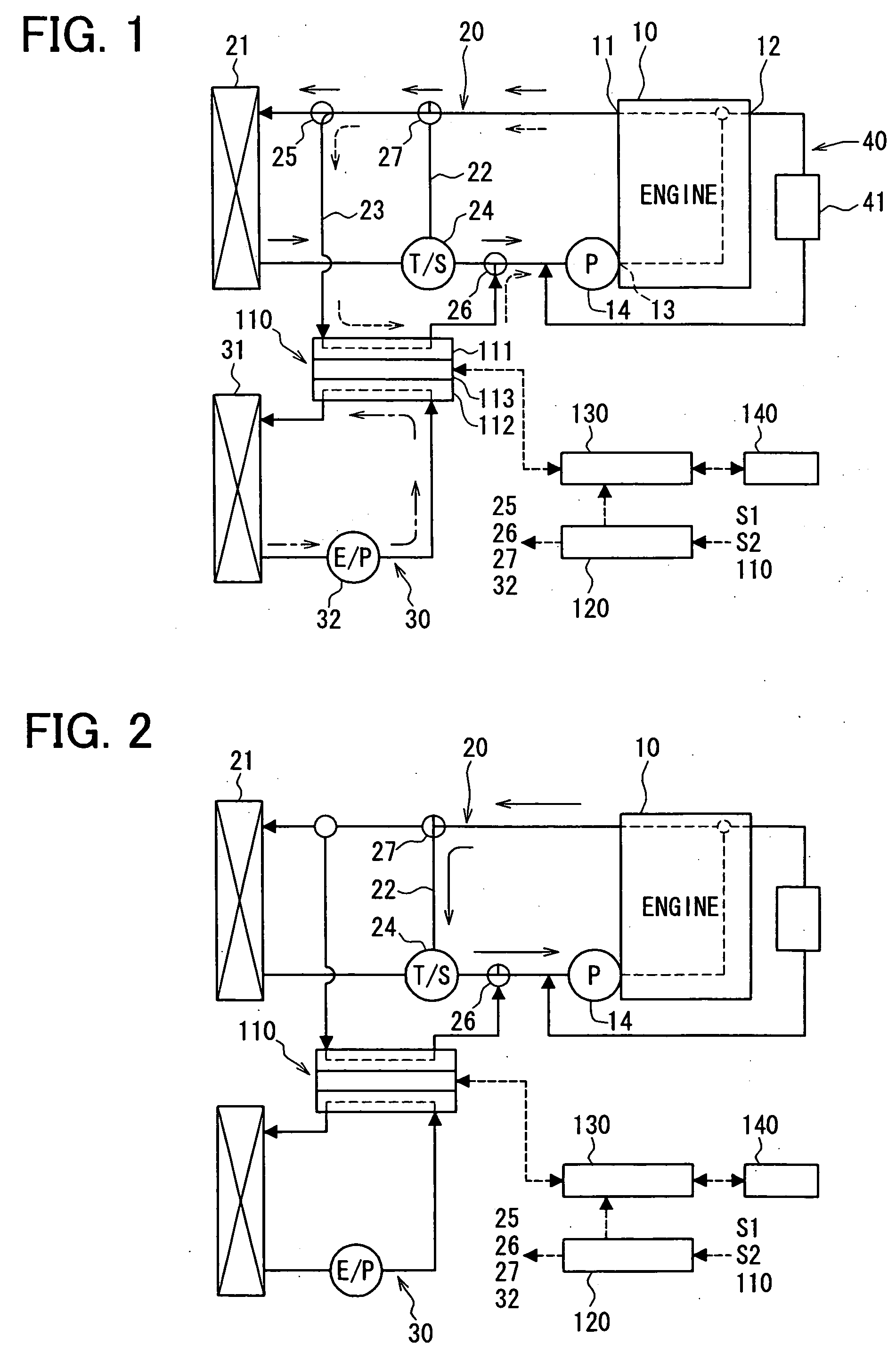
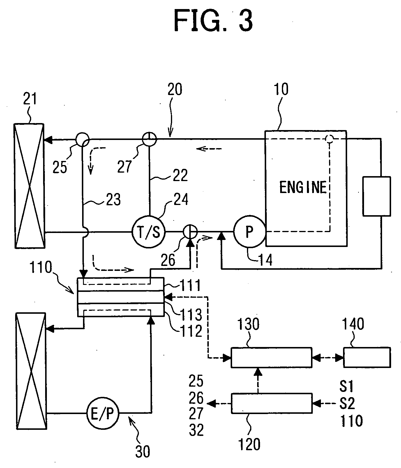
[0019] First, the basic configuration of the thermoelectric generator system 100 will be described with reference to FIG. 1. The engine 10 is provided with an engine cooling water circuit (first circuit) 20. A main passage of the engine cooling water circuit 20 is constructed such that ...


PUM


Abstract

A thermoelectric generator has a high temperature heat source part provided on a first passage through which a first fluid for cooling an engine flows, a low temperature heat source part provided on a second passage through which a second fluid having a temperature lower than that of the first fluid flows, and a thermoelectric element for producing electric power by a temperature difference produced between the high temperature heat source part and the low temperature heat source part. The first passage is included in a first circuit in which the engine and a first radiator for cooling the first fluid are connected in loop through a main passage. Further, the first passage is in parallel to the first radiator in the first circuit. The second passage is included in a second circuit that is separate from the first circuit and includes a second radiator for cooling the second fluid.

Description

CROSS REFERENCE TO RELATED APPLICATION [0001] This application is based on Japanese Patent Application No. 2004-372254 filed on Dec. 22, 2004, the disclosure of which is incorporated herein by reference. FIELD OF THE INVENTION [0002] The present invention relates to a thermoelectric generator that recovers electric energy from waste heat energy generated in an engine by using a thermoelectric element. BACKGROUND OF THE INVENTION [0003] It is known to recover electric energy from waste heat energy generated in an internal combustion engine (hereafter, engine) by a thermoelectric element. For example, in an engine cooling water circulation system disclosed in Japanese Unexamined Patent Publication No. JP-A-10-238406, electric energy is recovered by using cooling water, which circulates in a cooling water circuit connecting an engine and a first radiator, as a high temperature heat source part of a thermoelectric element and a second radiator, which is cooled by air or water, as a low ...

Claims


Application Information

Patent Timeline
IPC IPC(8): H01L35/30H01L35/28
CPCF01P3/20F01P7/165F01P2007/146F01P2025/50F02G5/00H01L35/00Y02T10/166Y02T10/12H10N10/00
Inventor YAMAGUCHI, HIROOYAMANAKA, YASUTOSHIMORI, RENTAROINAOKA, HIROYA
Owner DENSO CORP
Why Eureka
Try Eureka