Relief valve

a valve and valve body technology, applied in the direction of valve operating means/releasing devices, functional valve types, machines/engines, etc., can solve the problems of high pressure transients unwanted pressure loss in this stage, and significant pressure rise in the liquid fuel system. , to achieve the effect of relieving pressure, preventing significant pressure loss, and relieving thermal high pressure transients

Active Publication Date: 2006-06-22
JANSENS AIRCRAFT SYST CONTROLS
View PDF17 Cites 10 Cited by
  • Summary
  • Abstract
  • Description
  • Claims
  • Application Information

AI Technical Summary

Benefits of technology

[0013] The present invention is a bi-stable valve that is particularly suited for relieving pressure that can build up in the liquid side of the fuel system of a turbine engine during various stages of operation of the turbine. In particular, the valve works to relieve thermal high pressure transients while preventing significant pressure losses during turbine start-up and sustained operation.

Problems solved by technology

This is particularly a problem in the liquid fuel system given that liquids are generally not compressible.
First, since liquid fuel is typically consumed during turbine start-up, the pressure in the liquid fuel system will rise significantly after ignition.
Thus, normally pressure loss in this stage is unwanted.
Second, when the turbine is to be shut down or transitioned to operate in gaseous mode, high pressure transients can occur in the liquid fuel system due to the back flow of fuel back into the system caused by the shutting down of various pumps and metering devices, such fuel pumps, flow dividers, distributor valves and purge valves, in the liquid fuel system.
Third, after the turbine is switched to burn gaseous fuel, the ambient temperature surrounding the turbine rises due to the heat given off by the sustained operation of the turbine.
This increase in temperature can cause expansion of the liquid fuel and increase the pressure within the liquid fuel system.
The check valves are disadvantageous because they are one-way valves that open and close at a particular crack pressure and then return closed after the pressure subsides.
A single check valve would thus be insufficient for this purpose.
Additionally, common check valves are spring-loaded ball valves that may be unreliable in the harsh environment of large industrial turbines, particularly given the contaminants present in the liquid fuel and the propensity for coking.
Thus, such check valves may stick in the open position or allow backwash into either of the fuel lines.
However, the fuel cut-off valve is usually operated by a pneumatic actuator and thus is impractical for relieving pressure transients because of its difficultly to control precisely and because it would likely introduce a substantial pressure drop.
Like check valves, it is also subject to coking due to its relatively close position to the combustion area of the turbine.
Moreover, the fuel cut-off valve would also introduce a potential failure point to the turbine where, if pressure is lost to the pneumatic actuator, the turbine could cease operating.

Method used


Image

  • Relief valve
  • Relief valve
  • Relief valve

Examples


Embodiment Construction

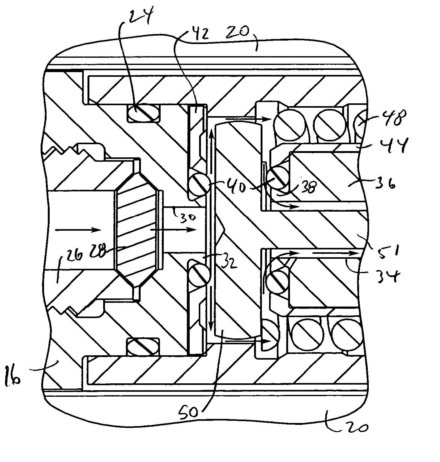
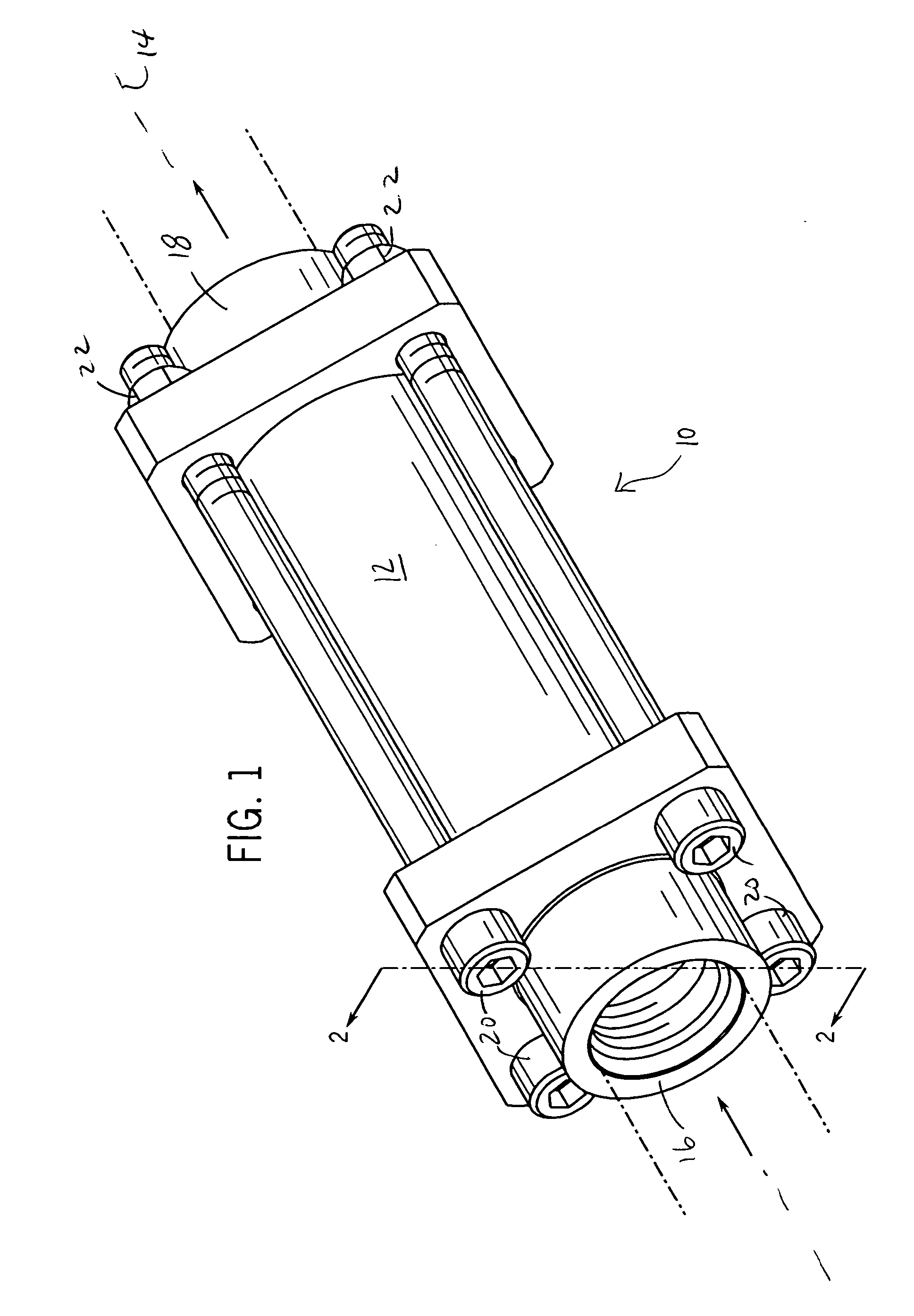
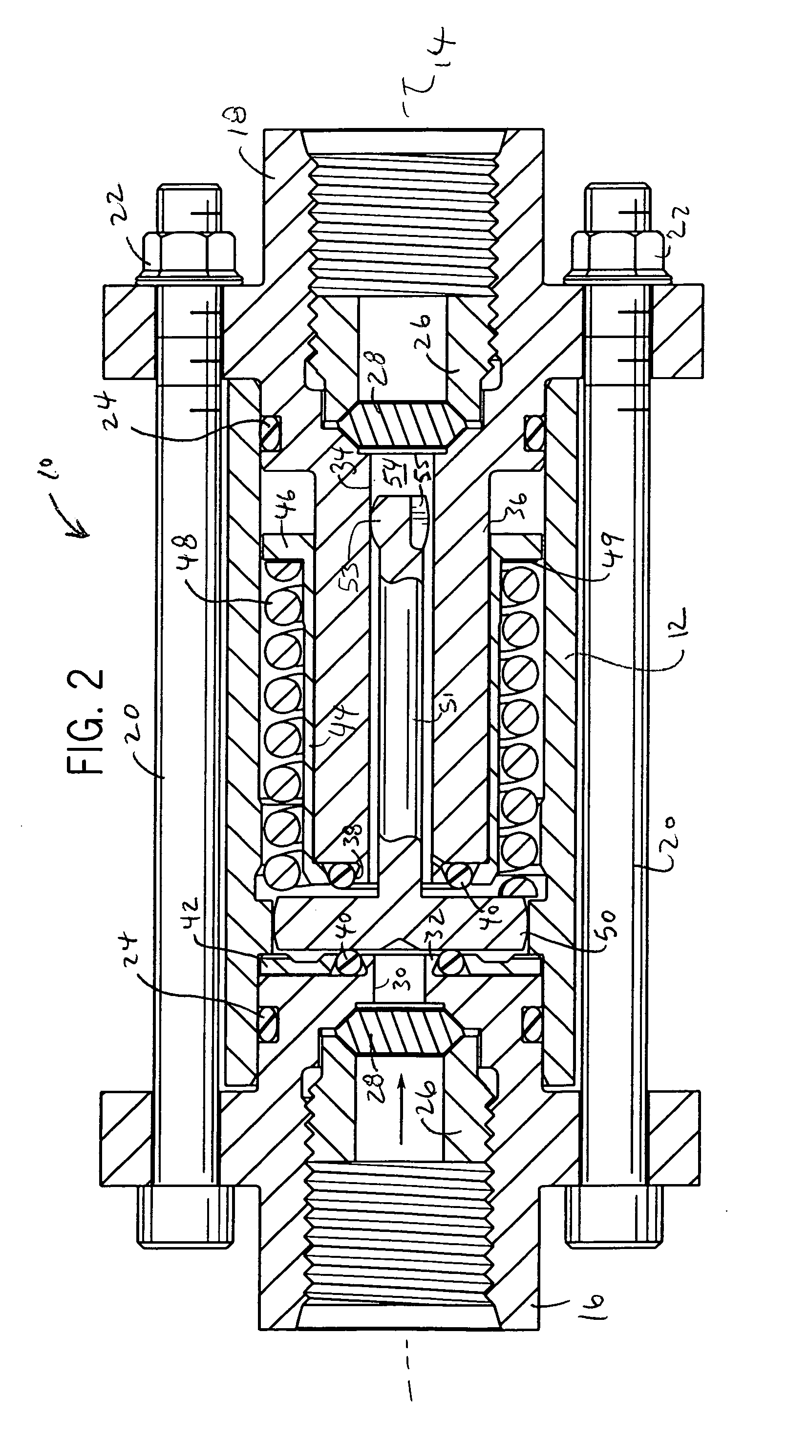
[0027] The present invention provides a relief valve 10 (see FIG. 1) particularly suited for use with dual fuel turbines in which the turbine consumes either liquid or gaseous fuel at one or more stages of operation. Such turbines are typically large industrial turbines used for power generation, and they typically burn liquid fuel (such as diesel fuel) during start-up and switch to gaseous fuel (such as natural gas) during sustained operation. In this context, the relief valve 10 is used to relieve transient high pressure in the liquid fuel system of the turbine, which can occur at start-up, the transition to gaseous fuel and as the liquid fuel is heated by the elevated ambient temperature surrounding the combustion areas of the turbine during operation on gaseous fuel. The valve is normally closed at turbine ignition when liquid fuel is used and during the dynamic transfer from gaseous to liquid fuel usage, and can be opened when high pressure transients arise during gaseous fuel ...


PUM


Abstract

A valve for the fuel system of a turbine engine works to relieve high pressure transients in the liquid fuel side of the turbine engine arising from the elevated ambient temperatures of operation of the turbine on gaseous fuel. The valve also prevents significant pressure losses during turbine start-up and sustained operation. The valve is bi-stable and has a liquid fuel driven poppet that toggles between one of two closed positions to interrupt flow through the valve when below a lower pressure limit and when above an upper pressure limit. The poppet moves to an intermediate position temporarily to permit pressure relief. A method of operating such a valve is also provided.

Description

CROSS-REFERENCE TO RELATED APPLICATION [0001] This application claims benefit to U.S. provisional application Ser. No. 60 / 617,298 filed Oct. 8, 2004.STATEMENT OF FEDERALLY SPONSORED RESEARCH OR DEVELOPMENT [0002] Not applicable. BACKGROUND OF THE INVENTION [0003] 1. Technical Field [0004] The present invention relates to turbine engines, and in particular, to valves for relieving high pressure transients in the liquid fuel side of the turbine. [0005] 2. Description of the Related Art [0006] Turbine engines are commonly used in power generation and propulsion applications. Generally, turbine engines have a set of rotating turbine blades that compress air leading to one or more combustors into which fuel is injected and ignited. Fuel is delivered through metering orifices to burners in the combustors under pressure through one or more fuel lines. Combustion of the fuel turns one or more sets of turbine blades, used for energy extraction or propulsion, and which can be used to drive th...

Claims


Application Information

Patent Timeline
Patent Type & Authority Applications(United States)
IPC IPC(8): F16K17/30
CPCF02C7/232F02C9/40F05D2260/85Y10T137/7867Y10T137/7932Y10T137/8122
Inventor JANSEN, HARVEY B.
Owner JANSENS AIRCRAFT SYST CONTROLS
Why Eureka
Try Eureka