
Power supply device

a technology of power supply device and power supply device, which is applied in the direction of vehicle heating/cooling device, thermoelectric device, transportation and packaging, etc., can solve the problems of fuel consumption deterioration, drivability deterioration, and the drive force supplied to each wheel of the engine drive force decreases, so as to achieve the effect of using the heat moun

Inactive Publication Date: 2006-06-22
TOYOTA JIDOSHA KK
View PDF4 Cites 10 Cited by
  • Summary
  • Abstract
  • Description
  • Claims
  • Application Information

AI Technical Summary

Benefits of technology

[0006] The present invention was conceived in view of solving the above problems and an object of the present invention is to provide a power supply device that makes it possible to suppress a deterioration in drivability and improve fuel consumption.
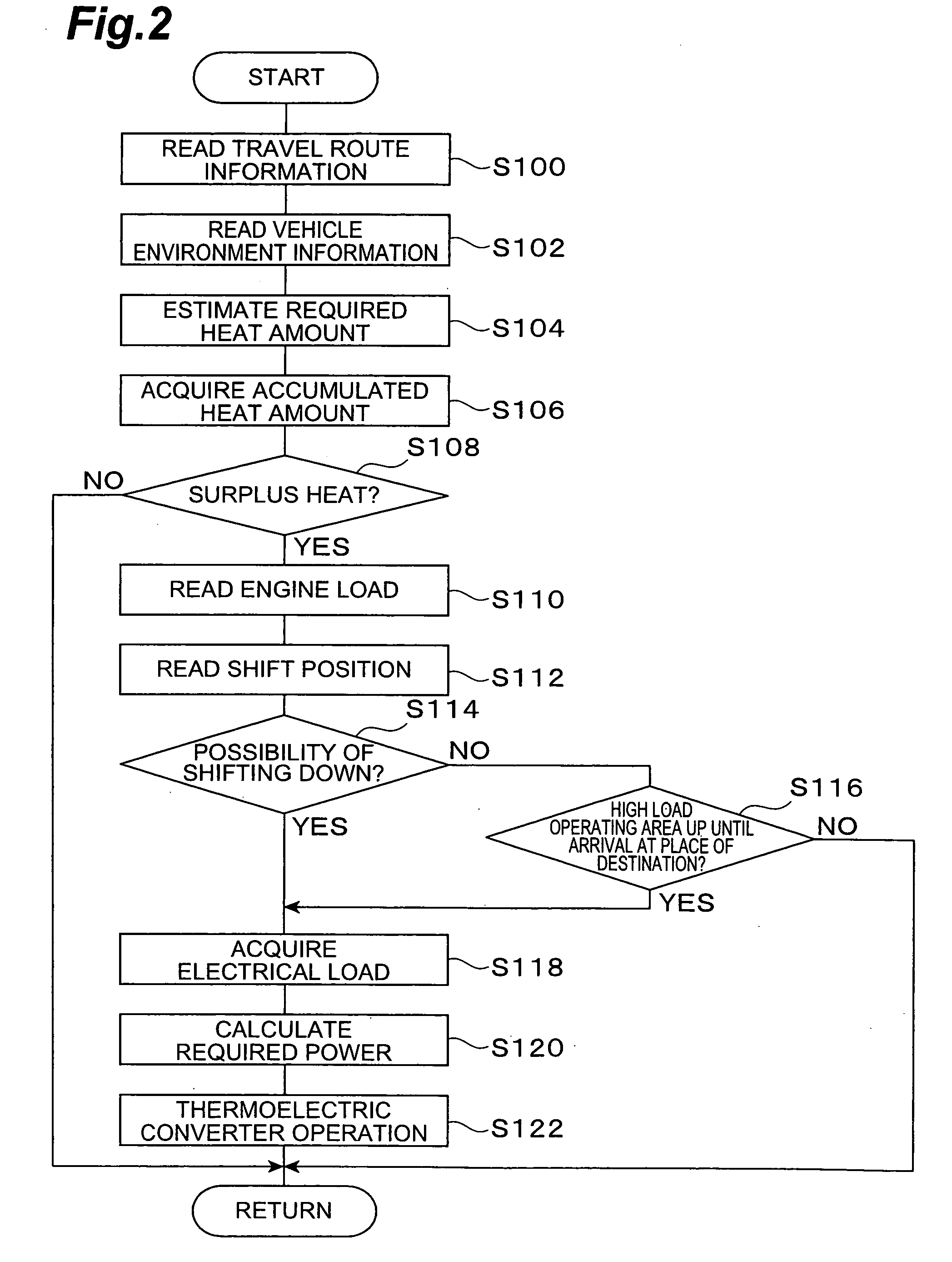
[0019] In this case, the heat amount required by the vehicle is predicted on the basis of the vehicle environment information such as the temperature in the vehicle, humidity in the vehicle, outside-air temperature, and air-conditioner set temperature, for example. The accumulated heat amount of the heat accumulator and the predicted required heat amount are compared and the surplus accumulated heat amount can be distributed to the power supply to the battery. As a result, power can be supplied to the battery from the thermoelectric converter by effectively using the heat mount that has accumulated in the heat accumulator while securing the heat amount required by the vehicle.

Problems solved by technology

For example, when the drive load of the alternator increases, the drive force supplied to each wheel of the engine drive force decreases and drivability deteriorates.
Moreover, when the driver, in sensing a lack of drive force, then steps on the accelerator pedal in order to compensate for the lack of drive force, fuel consumption deteriorates.

Method used


Image

  • Power supply device
  • Power supply device
  • Power supply device

Examples


Embodiment Construction

[0028] Preferred embodiments of the present invention will be described hereinbelow with reference to the drawings. The same reference symbols have been used for parts that are the same or equivalent in the drawings.

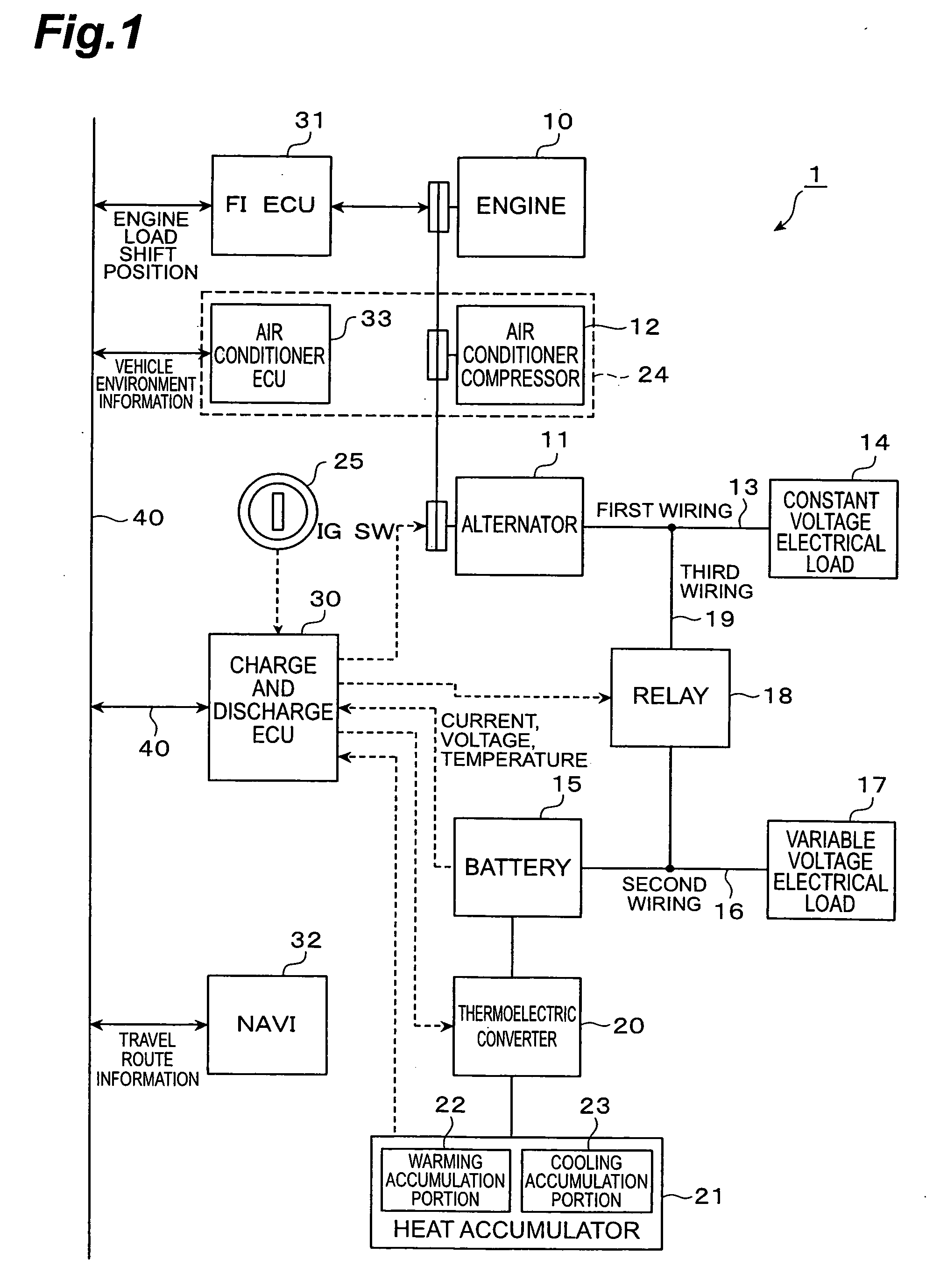
[0029] First, the constitution of a power supply device 1 according to this embodiment will be described by using FIG. 1. FIG. 1 is a block diagram showing the overall constitution of the power supply device 1 mounted in a vehicle.

[0030] The drive force driving the vehicle is generated by an engine 10 constituting an internal combustion engine. The engine 10 itself is a general engine that is publicly known. The output of the engine 10 is transmitted to the drive wheels via the transmission or differential gear and so forth to drive the vehicle. Further, an alternator (power generator) 11 and an air conditioner compressor 12, which are driven by using a portion of the output of the engine 10, are provided attached to the engine 10.

[0031] The alternator 11 contains a r...


PUM


Abstract

The power supply device comprises first wiring that connects an alternator that is driven by the engine and a constant voltage electrical load that is driven at 12V, a heat accumulator that accumulates cooling heat and warming heat, a thermoelectric converter which generates power by using the heat that has accumulated in the heat accumulator and which supplies the generated power to the battery, second wiring that connects the battery and a variable voltage electrical load that is driven at 5V to 16V, for example, a relay which is provided on third wiring that connects the first wiring and second wiring and which interrupts the first wiring and second wiring, and a charge and discharge ECU which controls the thermoelectric converter on the basis of travel route information and so forth and which controls the relay on the basis of the operating state of the engine, the heat accumulation state of the heat accumulator, and the state of charge of the battery.

Description

BACKGROUND OF THE INVENTION [0001] 1. Field of the Invention [0002] The present invention relates to a power supply device and, more particularly, to a vehicle power supply device. [0003] 2. Related Background of the Invention [0004] Conventionally, an alternator (AC power generator), which generates an AC current as a result of being driven by the motive power of the engine, is used to supply electrical power to a variety of electrical components mounted in a vehicle (Japanese Patent Application Laid Open No. H8-79915). The alternator rectifies the generated AC current by means of a diode to convert the AC current to a DC current, supplies the DC current to each electrical component and charges the battery. SUMMARY OF THE INVENTION [0005] The electrical load of each of the electrical components to which power is supplied from the alternator fluctuates as a result of the operating state and so forth of the vehicle. Hence, the load required to drive the alternator also fluctuates. Fo...

Claims


Application Information

Patent Timeline
IPC IPC(8): H02J7/04
CPCB60H2001/2275B60L1/00B60L2210/20B60L2260/56B60W10/06B60W10/08B60W10/30H01L2924/0002H01L35/00H02J7/1446Y02T10/725H01L2924/00H02J2310/48Y02T10/72H10N10/00H02J7/16H02J7/14
Inventor TSUBONE, KENJI
Owner TOYOTA JIDOSHA KK
Learn More