Radar detector with signal source location determination and filtering

a technology of signal source and detector, applied in direction finders, instruments, communication jamming, etc., can solve problems such as undermining the credibility of radar detector performance, radar detectors cannot tell the difference between emissions from many of these devices and true police radar systems, and radar detectors are increasingly generating false alarms

Inactive Publication Date: 2006-06-22
STERN ARI K +1
View PDF23 Cites 34 Cited by
  • Summary
  • Abstract
  • Description
  • Claims
  • Application Information

AI Technical Summary

Problems solved by technology

The growing number of such signals is rapidly undermining the credibility of radar detector performance.
Radar detectors cannot tell the difference between emissions from many of these devices and true police radar systems.
As a result, radar detectors are increasingly generating false alarms, effectively “crying wolf”, and reducing the significance of warnings from radar detectors.
This has reduced the significance of the K-Band warning and further undercut the overall benefit to the user of a radar detector.
Older detectors, however, do not incorporate this feature and could be obsolete in areas where ARTIMIS is in use.
These are sometimes referred to as “polluting radar detectors,” and present a serious threat to some detector products.
A similar problem occurred in the early 1990's when the Ka band was widened.
However there are certain types of equipment that can cause the amplifiers and detection circuitry used in a laser detector to generate a “false” detect.
In particular, certain locations near airports have been demonstrated to cause such problems for various laser detector products.
Each of these changes and enhancements has the potential effect of making obsolete existing detectors that do not include appropriate countermeasures.
Furthermore, some sources, particularly, stationary door opener sources, at this time, cannot be filtered economically and, thus, threaten the usefulness of even the most sophisticated modem radar detector.
A drawback of these warning systems is that stationary transmitters of these signals send the same message to drivers constantly, and become a nuisance during daily commute.
However these messages become an annoyance to drivers who follow the same path to work everyday.
Thus, radar detector manufacturers are continually confronted with new problems to solve, due to the variety of different types of unrelated sources and their sheer numbers.
Meanwhile, the market for radar detectors is shrinking because consumers are no longer interested in buying products that so quickly become obsolete.

Method used


Image

  • Radar detector with signal source location determination and filtering
  • Radar detector with signal source location determination and filtering
  • Radar detector with signal source location determination and filtering

Examples


Embodiment Construction

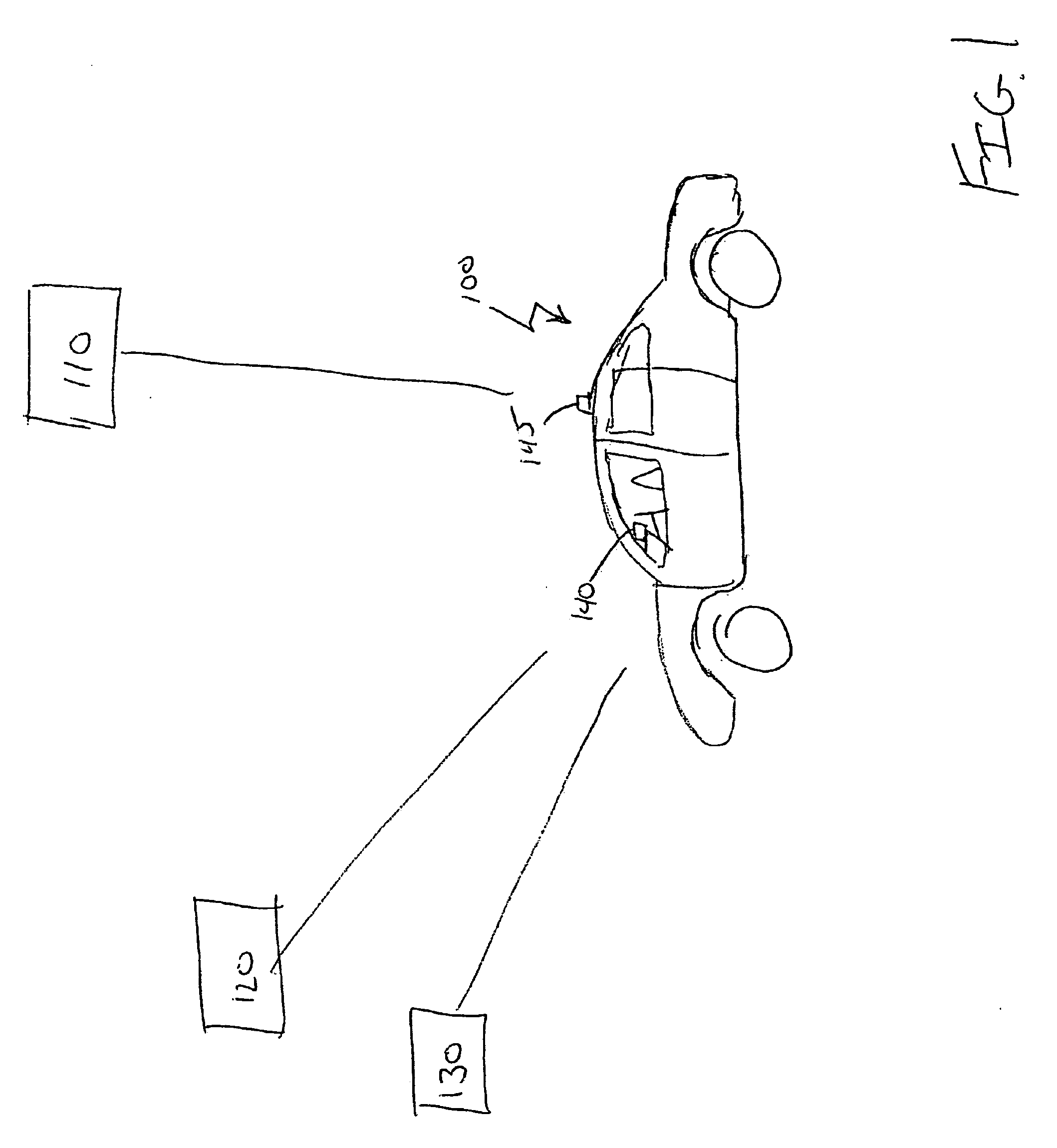
[0031] Referring now to FIG. 1, a vehicle 100 is illustrated in operation on a roadway, under exposure to a radio frequency signals from a variety of sources. These include a GPS satellite system 110, police radar signals from a radar gun 120, and non-police sources of interference 130. These non-police interference signals can be generated by a variety of sources such as automatic doors or security systems. Vehicle 100 also includes a radar detector 140 which is able to identify the present location and / or the velocity of the vehicle 100, using a GPS receiver 145 connected to the unit. However, other land-based signals such as LORAN can be used instead. The radar detector 140 uses this information to determine if the received signal is proper police signal 120 or is merely interference from a non police signal 130.

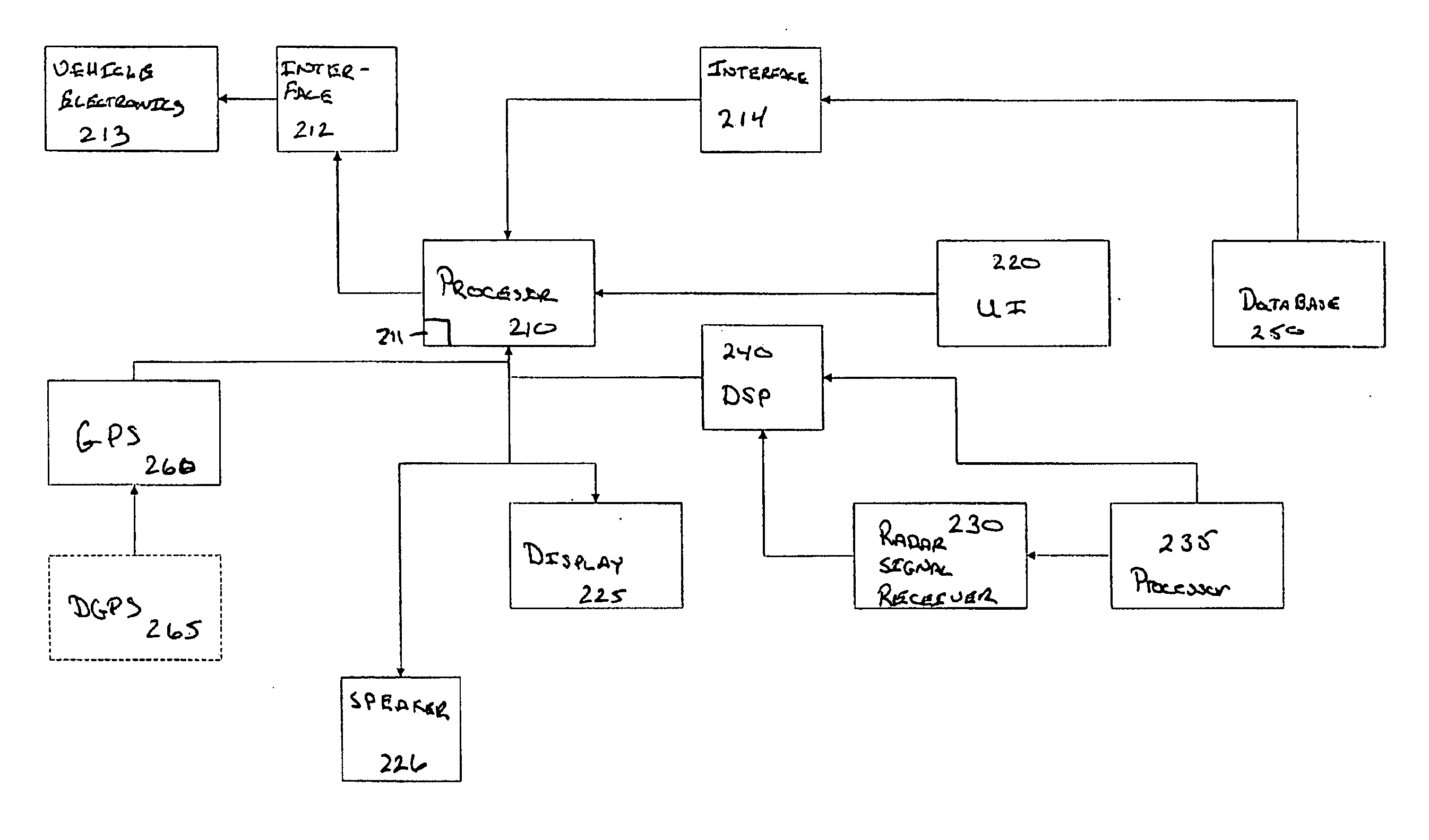
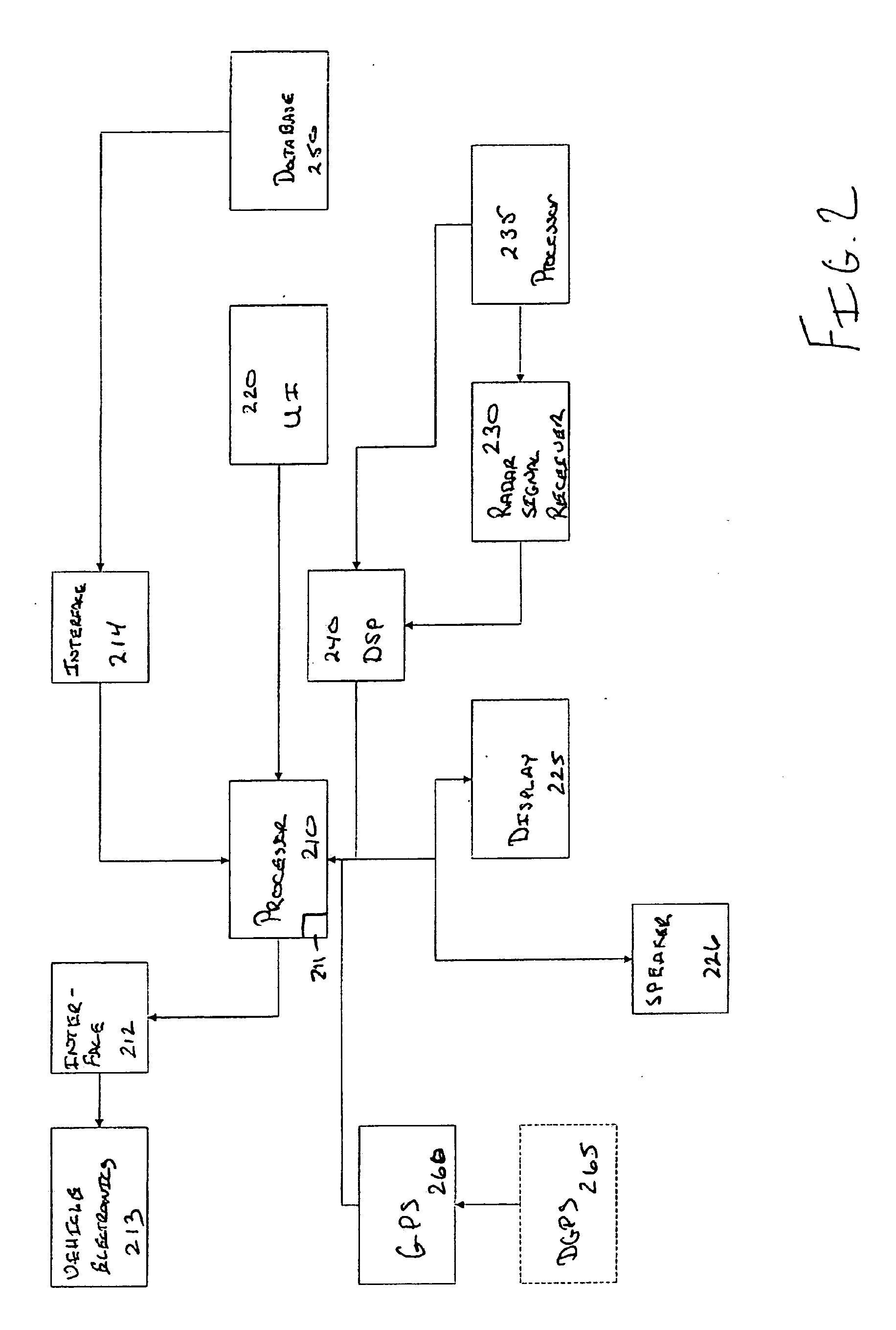
[0032]FIG. 2 is a block diagram illustrating the components of the radar detector 140 according to one embodiment of the present invention. Radar detector 200 correspond...


PUM


Abstract

A radar detector and location unit includes at least three sensors configured to detect a radar signal, at least three sensors being aligned in a non liner arrangement; a position receiver configured to determine a position of the radar detector; a data storage device configured to store data related to a location of a known series of radar emissions sites; a processor connected to the at least three sensors, the position receiver and the data storage device. The processor is configured to determine the location of the radar emission based on a coordination between the at least three sensors and the position of the radar detector. The processor is further configured to compare the location of the radar emission with locations in a known series of radar emissions sites.

Description

CROSS REFERENCE TO RELATED APPLICATION [0001] This application is a completion application of copending U.S. Provisional Patent Application No. 60 / 638,852, filed on Dec. 22, 2004, the entire disclosure of which is hereby incorporated by reference.BACKGROUND OF THE INVENTION [0002] 1. Field of the Invention. [0003] The present invention is for radar detectors. More specifically, the present invention is directed to a radar detector that can determine the location of a radar signal and filter the signal based upon a list of known false radar sources. [0004] 2. Prior Art. [0005] Radar detectors warn drivers of the use of police radar, and the potential for traffic citations if the driver exceeds the speed limit. The FCC has allocated several regions of the electromagnetic spectrum for police radar use. The bands used by police radar are generally known as the X, K and Ka bands. Each relates to a different part of the spectrum. The X and K bands are relatively narrow frequency ranges, w...

Claims


Application Information

Patent Timeline
Patent Type & Authority Applications(United States)
IPC IPC(8): G01S7/40G01S13/42
CPCG01S3/50G01S5/04G01S7/022G01S19/14
Inventor STERN, ARI K.STERN, AUDRA R.
Owner STERN ARI K
Why Eureka
Try Eureka