Radar detector with reduced emissions

a detector and emission reduction technology, applied in the field of detectors, can solve the problems of radiation leakage, significant radiation outward emission of such detectors, and possible cracks or gaps in the case, and achieve the effect of reducing the amount of undesired signal radiation

Active Publication Date: 2008-06-17
ESCORT INC
View PDF16 Cites 17 Cited by
  • Summary
  • Abstract
  • Description
  • Claims
  • Application Information

AI Technical Summary

Benefits of technology

[0013]The use of LNA's in accordance with these aspects of the invention mitigates detector radiation in a number of ways. The use of an LNA on the forward signal path from an antenna to a mixer, works to isolate against reverse propagation of signal from the local oscillator through the mixer to the antenna along the same path. The use of separate antennae for separate bands, permits the use of separate paths from the respective LNA's for those bands to the mixer(s). Each path is required to pass signals at the desired receiving frequencies, while attenuating signals outside of this range. In the disclosed embodiment, this filtering is accomplished with microstrip filters, and the use of separate paths for individual bands, or combination thereof, significantly reduces the filter complexity, and generally increases out of band attenuation, reduces insertion loss, and reduces filter size.
[0015]Frequencies below which the channel width is less than one half wavelength are said to be in cutoff. The attenuation of signals that are in cutoff depends on how far the signal frequency is below the cutoff frequency, and the length of the channel. To reduce the amount of undesired signal radiated through the channel, the channel is as narrow and long.

Problems solved by technology

Even if the case is of metal or other conductive material, emissions may escape through cracks or gaps in the case.
While radar detectors are mobile products and thus not FCC regulated, there have been issues of interference between radar detectors (one detector creating a false signal on another), as well as complaints of VSAT (very small aperture terminal) ground terminal operators about possible interference originating from radar detectors.
While the patents and products heretofore known have disclosed various detector circuit architectures, and those architectures may have exhibited increasing detection performance, there remains significant outward emission of radiation from such detectors, primarily owing to feedthrough from the local oscillator to the antenna and leakage through the case.
As to the latter issue, while detectors have been made with metal or conductive cases to form a Faraday cage around the detector circuits, gaps in the case undermine the Faraday cage effect and can permit radiation leakage.
This approach may improve the Faraday effect of the case, but at the potential expense of impeding maintenance or upgrading of the detector if either requires opening the case.

Method used


Image

  • Radar detector with reduced emissions
  • Radar detector with reduced emissions
  • Radar detector with reduced emissions

Examples


Embodiment Construction

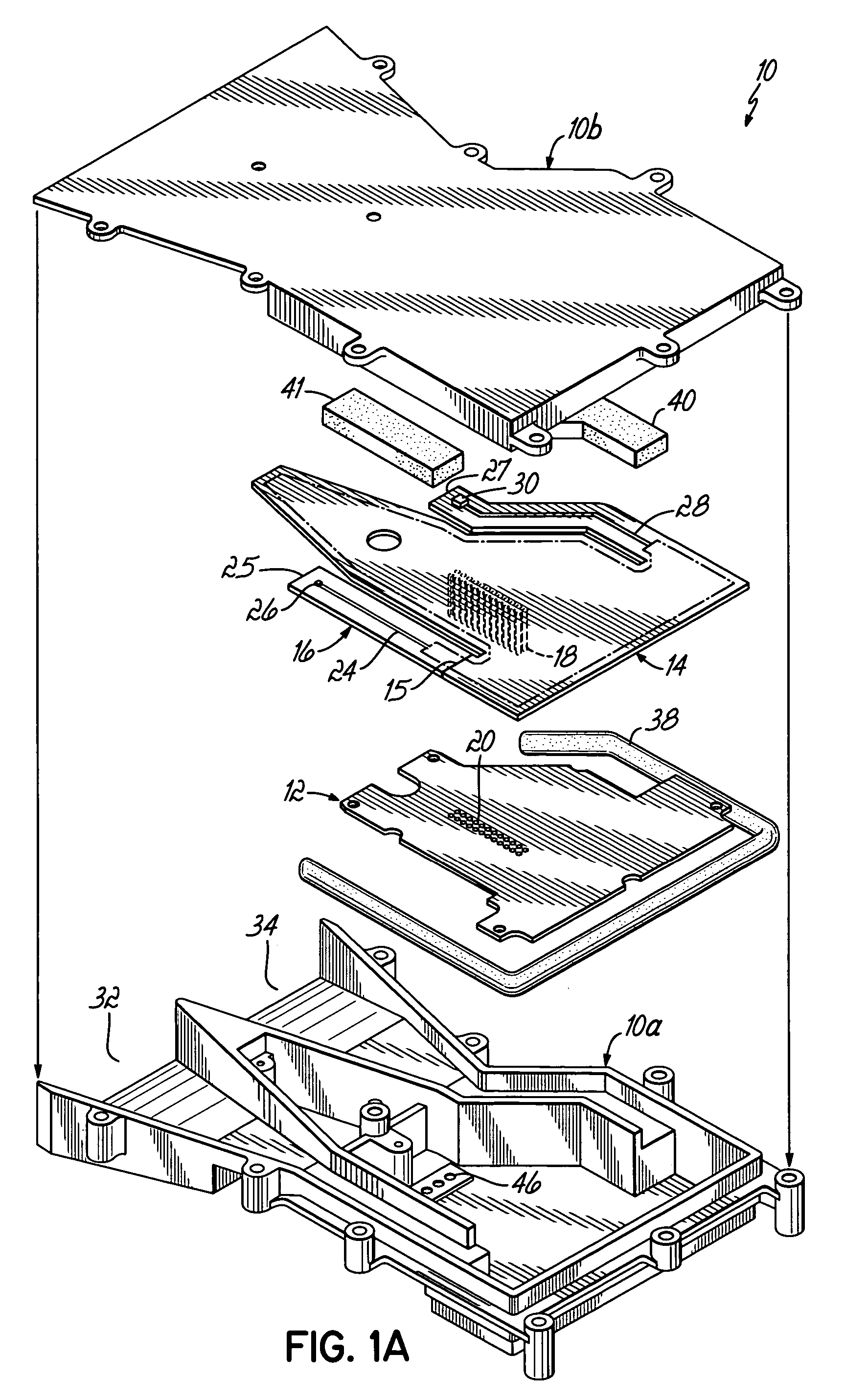
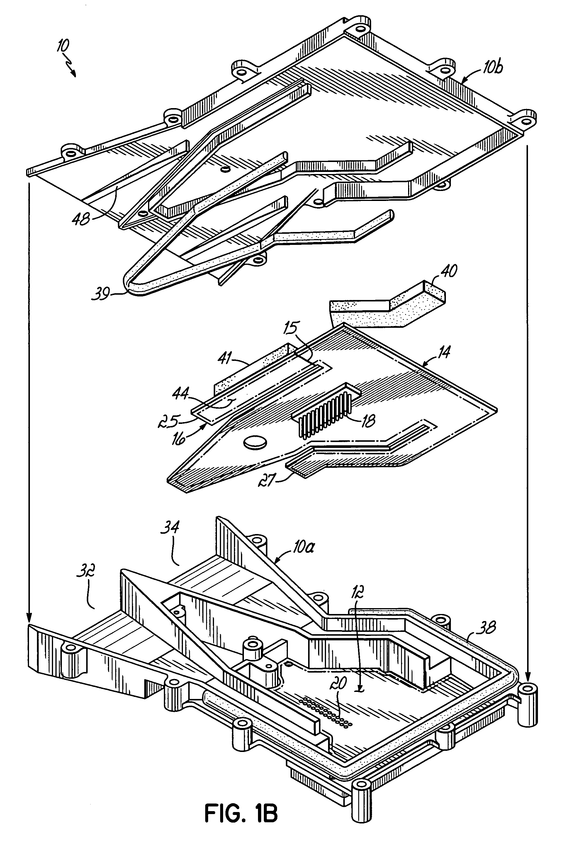
[0029]Referring to FIG. 1A, a radar detector 10 in accordance with principles of the present invention utilizes a metal or other conductive material case that is formed in two halves 10A and 10B. The case encloses the circuit boards forming the detection circuitry of a radar detector, including a digital circuit board 12, a RF circuit board 14 and a K / Ka band RF circuit board 16. Circuit board 16 is affixed to circuit board 14 by a solder joint 15 between those two boards, that effectively connects the signal traces on board 16 to the signal traces on board 14. Digital board 12 is coupled to RF board 14 by a matrix of pins 18 best shown in FIG. 1B, which insert into a matrix of sockets 20 in digital board 12. K / Ka RF board 16 is formed separately from RF board 14 to permit the use of a different layering on K / Ka board 16, for more optimal conveyance of K / Ka frequency radar signals. Furthermore RF board 14 is formed separately from digital board 12 to similarly permit the use of diff...


PUM


Abstract

A radar detector includes features to reduce emissions such as those typically generated by the detector's local oscillator. Two low noise amplifiers (LNA's), operating in X band and a combined K / Ka band, respectively amplify X and K / Ka band signals from separate antennae, and deliver those signals over separate, elongated and narrow signal paths to X and K / Ka mixers, where those signals are mixed with local oscillator (LO) signals to produce IF for detection. The elongated, narrow signal paths from the antennae to the mixers reduce LO emissions, and those emissions are further reduced by incorporating radar absorbers between the circuit board and detector case along the antenna-mixer path, including radar absorptive paint on the circuit board itself along this path, and sealing the case with a conductive sealing gasket.

Description

FIELD OF THE INVENTION[0001]The present invention relates to detectors for detecting police radar signals.BACKGROUND OF THE INVENTION[0002]Police traffic surveillance devices emit an electromagnetic signal in the radio frequency (RF) band or light band (i.e., infrared, visible, and ultraviolet light) that reflect off of approaching or departing vehicles to determine their speed. In particular, a change in frequency (Doppler shift) or a change in time of travel for return signal pulses is sensed for calculating vehicle speed. The following RF (radar) frequency bands are used: X-band (10.525 GHz±25 MHz); K-band (24.150 GHz±100 MHz); and Ka-band (34.700 GHz±1300 MHz). Furthermore, laser wavelength of 904 nm with 33 MHz bandwidth is also used.[0003]Police radar and laser detectors (“detectors”) are used by drivers of vehicles to detect radiant electromagnetic signals characteristic of police traffic surveillance devices. These detectors are generally a detachable device clipped to a vis...

Claims


Application Information

Patent Timeline
Patent Type & Authority Patents(United States)
IPC IPC(8): G01S7/292
CPCG01S7/022H04B1/26
Inventor MARTINSON, GLEN D.BURIN, MARIAN MARKLISOWSKI, FELIKS K.
Owner ESCORT INC
Why Eureka
Try Eureka