Image pickup apparatus and image pickup method

a technology of image pickup and image, which is applied in the direction of color television details, television systems, and conversion with storage devices, etc., can solve the problems of high power consumption time required to play back picked up images, and high cost of image pickup apparatus, so as to reduce the rate of reading image signals from memory, the effect of easy reading and easy change of frame ra

Inactive Publication Date: 2006-06-22
SONY CORP
View PDF7 Cites 16 Cited by
  • Summary
  • Abstract
  • Description
  • Claims
  • Application Information

AI Technical Summary

Benefits of technology

[0013] According to an embodiment of the present invention, there is provided a plurality of converting units (steps) converting the frame rate of image signals by controlling writing the image signals in a memory and reading the image signals written in the memory. The image signals of picked up images are assigned to the plurality of converting units (steps) so that the image signals are arranged in order of sequential pixels when the image signals are read in the plurality of converting units (steps). Therefore, image signals of sequential pixels can be obtained by reading the image signals in each converting unit (step). In this case, the rate of reading the image signals from the memory can be decreased compared to a case where image signals of a predetermined number of pixels are assigned to the plurality of converting units (steps) in order of pixels. Accordingly, the picked up images stored in the memory can be easily read at a desired frame rate. Further, switching among the converting units (steps) where image signals are to be read is not required. Pixel signals of a plurality of sequential pixels are output in parallel as image signals and the image signals are assigned. With this configuration, even if the pickup frame rate increases by outputting pixel signals of a plurality of sequential pixels in parallel, the frame rate can be easily changed because image signals of a plurality of sequential pixels can be obtained when the image signals are read in each converting unit (step).

Problems solved by technology

Such an image pickup apparatus is expensive and power consumption thereof is high.
However, when picked up images are supplied to the computer apparatus and then signal processing and generation of a video signal are performed therein, time is required to play back the picked up images.

Method used


Image

  • Image pickup apparatus and image pickup method
  • Image pickup apparatus and image pickup method
  • Image pickup apparatus and image pickup method

Examples


first embodiment

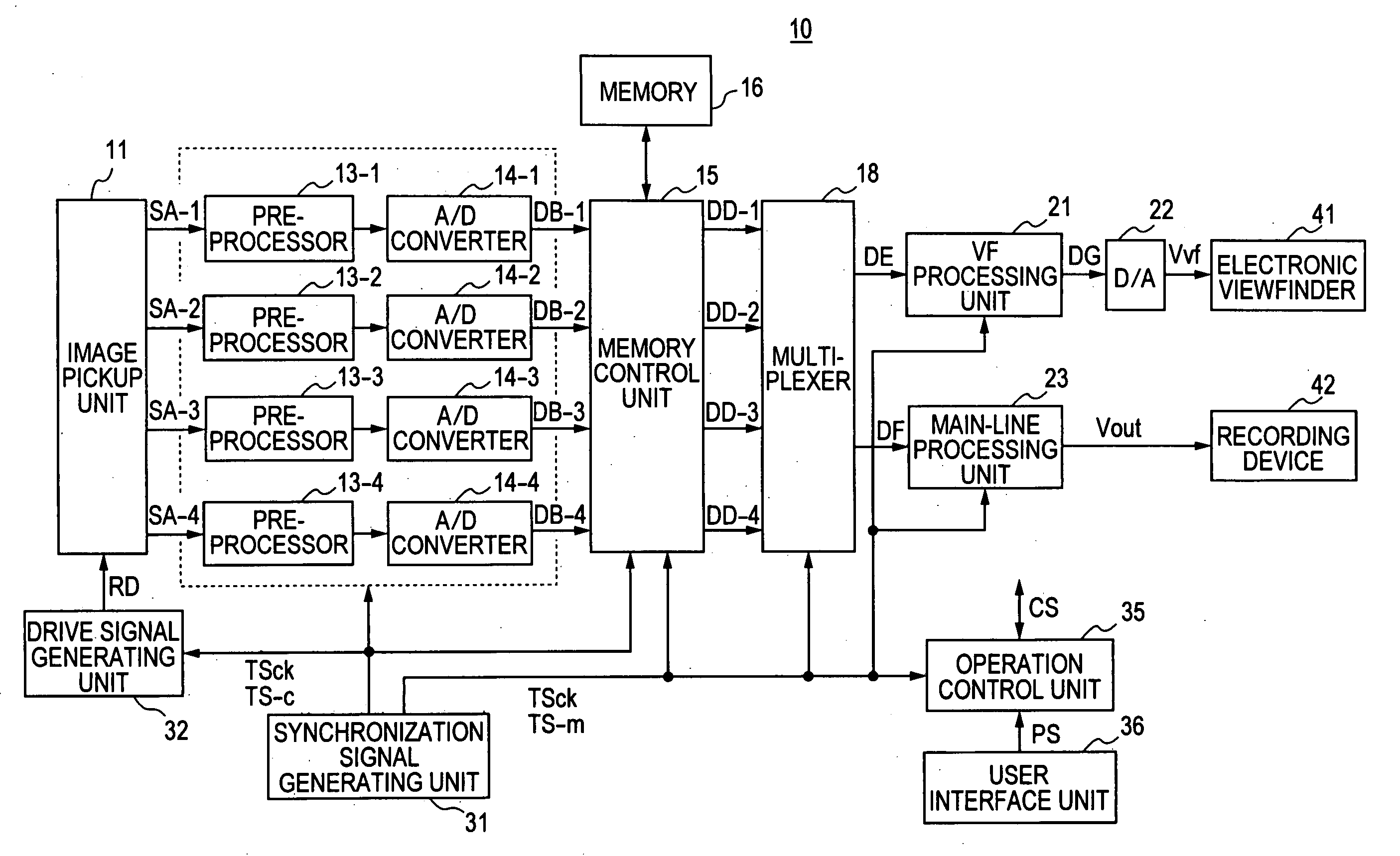
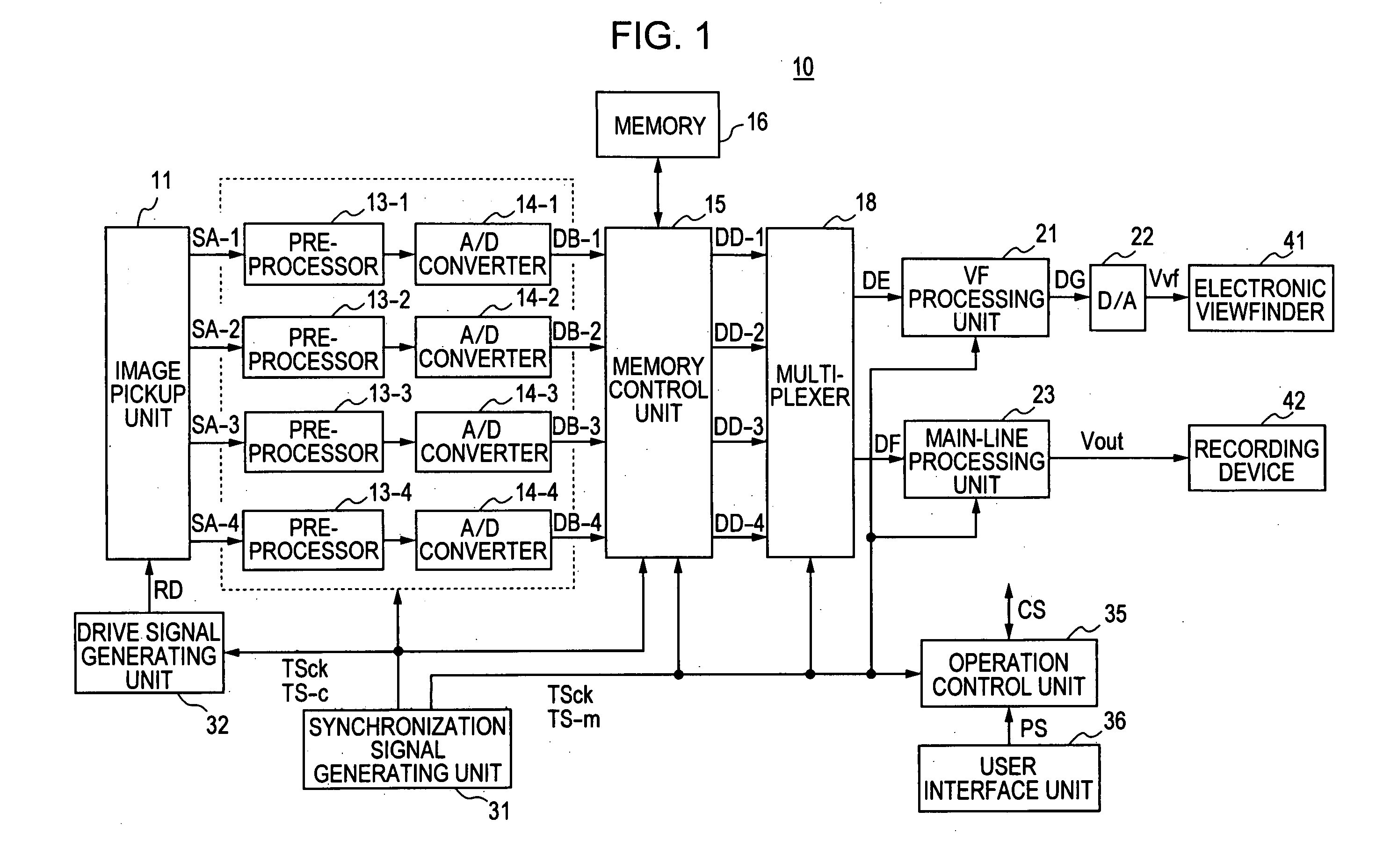
[0029] Hereinafter, a first embodiment of the present invention is described with reference to the drawings. FIG. 1 is a block diagram showing the configuration of an image pickup apparatus 10.

[0030] An image pickup unit 11 generates image signals of a pickup frame rate by using a CMOS or CCD solid state image pickup device. The pickup frame rate is equal to or higher than a recording frame rate used to record picked up images in a recording medium and a display frame rate used to display images in a viewfinder.

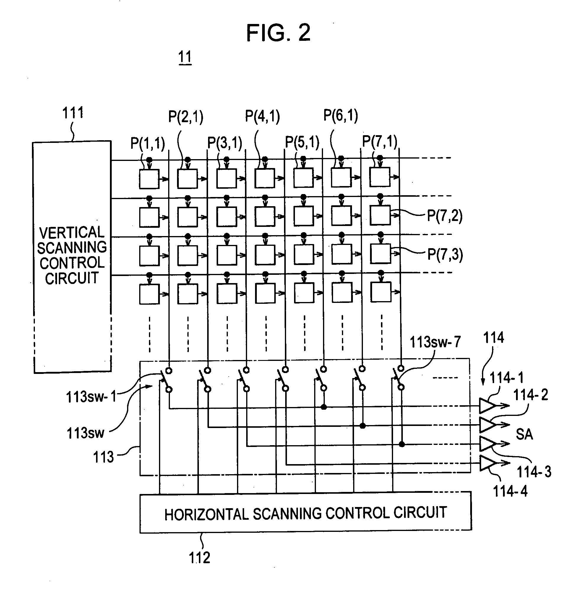
[0031]FIG. 2 is a block diagram showing an example of the configuration of the image pickup unit 11 using a CMOS solid state image pickup device of a column amplifier system or the like. In this image pickup unit 11, pixel signals of four pixels are output in parallel in one clock, for example. Accordingly, the pickup frame rate thereof is four times higher than that of an image pickup unit that outputs a pixel signal of one pixel in one clock.

[0032] A vertical scanning co...

second embodiment

[0072] Hereinafter, a second embodiment of the present invention is described with reference to the drawings. FIG. 9 is a block diagram showing the configuration of an image pickup apparatus 10.

[0073] An image pickup unit 11 generates image signals of a pickup frame rate by using a CMOS or CCD solid state image pickup device. The pickup frame rate is equal to or higher than a recording frame rate used to record picked up images in a recording medium or a display frame rate of images displayed in a viewfinder.

[0074]FIG. 10 is a block diagram showing the configuration of the image pickup unit 11 using a CMOS solid state image pickup device of a column amplifier system or the like. In this image pickup unit 11, pixel signals of sixteen pixels are output in parallel in one clock, for example. Accordingly, the pickup frame rate thereof is sixteen times higher than that of an image pickup unit that outputs a pixel signal of one pixel in one clock.

[0075] A vertical scanning control circ...


PUM


Abstract

An image pickup apparatus includes an image pickup device generating image signals of picked up images; a converting unit converting the image signals generated by the image pickup device to digital image signals; a memory storing the image signals obtained by the converting unit; and a memory control unit controlling writing the image signals in the memory and reading the image signals from the memory. The memory control unit assigns bands of the memory in order to simultaneously perform writing image signals in the memory and reading the image signals from the memory for displaying picked up images and/or reading the image signals from the memory for recording picked up images at different frame rates.

Description

CROSS REFERENCES TO RELATED APPLICATIONS [0001] The present invention contains subject matter related to Japanese Patent Applications JP 2004-340766 and JP 2004-340767 filed in the Japanese Patent Office on Nov. 25, 2004, the entire contents of which are incorporated herein by reference. BACKGROUND OF THE INVENTION [0002] 1. Field of the Invention [0003] The present invention relates to an image pickup apparatus and an image pickup method. More specifically, the present invention relates to enabling to display or record images picked up at high rate in real time by assigning bands of a memory in order to simultaneously perform writing image signals in the memory and reading the image signals from the memory for displaying picked up images and / or reading the image signals from the memory for recording picked up images at different frame rates. [0004] 2. Description of the Related Art [0005] In an image pickup apparatus, the movement of a subject can be displayed at a rate different f...

Claims


Application Information

Patent Timeline
Patent Type & Authority Applications(United States)
IPC IPC(8): H04N5/76
CPCH04N5/772H04N7/0105H04N5/907
Inventor IKEYAMA, HIROMASATAKAHASHI, KAZUSHIGEHARA, MANABUNISHIDE, YOSHIAKI
Owner SONY CORP
Why Eureka
Try Eureka