Laser triangulation method for measurement of highly reflective solder balls

a technology of highly reflective solder balls and laser triangulation, which is applied in the direction of measuring devices, instruments, using optical means, etc., can solve the problems of low signal quality, uneven and rough surface of solder balls, and strong diffused incident light scattering

Inactive Publication Date: 2006-06-22
RUDOLPH TECHNOLOGIES INC
View PDF4 Cites 11 Cited by
  • Summary
  • Abstract
  • Description
  • Claims
  • Application Information

AI Technical Summary

Benefits of technology

[0010] In accordance with an example embodiment of the present invention, the laser beam at the first laser beam intensity having low power may produce the best data when directed at the solder ball to a position other than an apex of the solder ball. Additionally, the laser beam at the second laser beam intensity having high power may produce the best data when directed at the solder ball at an apex of solder ball.

Problems solved by technology

In previous area array package designs, solder ball surfaces were relatively uneven and rough.
When illuminated by a laser beam, for instance, the uneven and rough solder ball surfaces resulted in a strongly diffused and scattered incident light.
The receiver arrangement signal reception intensity and signal-to-noise ratio are low, resulting in very low signal quality.
The large amount of reflected laser light often saturates the receiver arrangement and consequently the position sensing devices, resulting in poor overall signal quality at this location on the solder ball surface.
A single laser beam intensity may not be able to provide high quality receiver signals over the entire ball surface.
Conventional methods and apparatus for obtaining three dimensional object surface determination, such as illustrated in FIG. 1, such as found in U.S. Pat. No. 4,991,968 have a significant drawback of being costly to produce due to the number of components used.
Additionally, these conventional systems are bulky to operate and do not adapt to chip scale packages used today.

Method used


Image

  • Laser triangulation method for measurement of highly reflective solder balls
  • Laser triangulation method for measurement of highly reflective solder balls
  • Laser triangulation method for measurement of highly reflective solder balls

Examples


Embodiment Construction

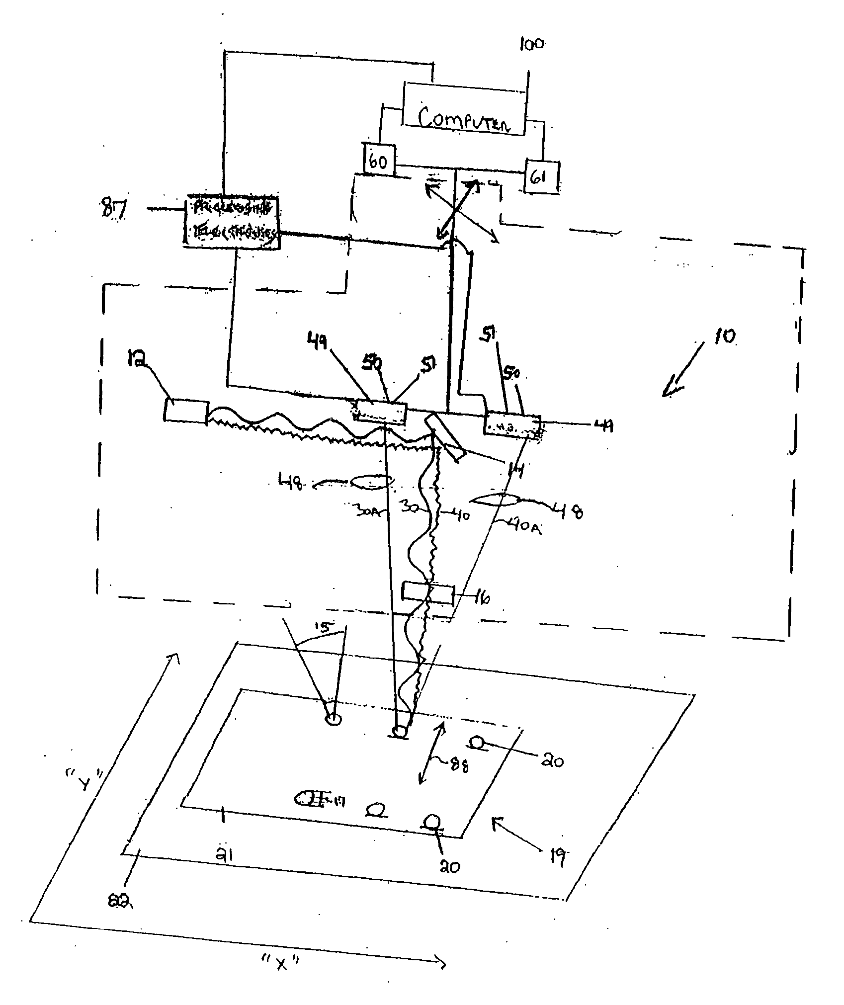
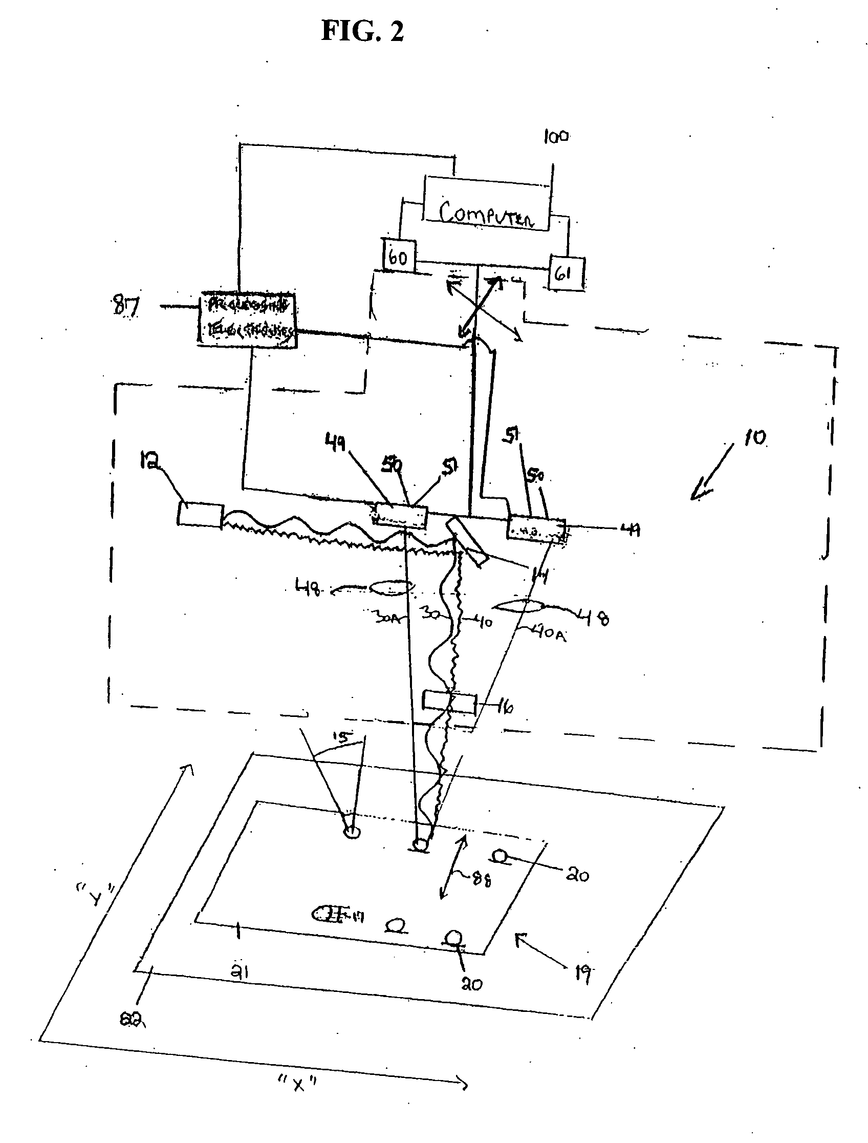
[0026] Referring to FIG. 2, the present invention may improve the measurement quality of laser triangulation systems 10 used to measure highly reflective solder balls 20. The present invention may allow solder balls placed upon electrical components for example to be measured with a high precision as a function of reflective light from a laser beam directed at the solder ball surface. In an embodiment of the present invention, the reflected signal 30A of a high intensity laser beam 30 is used for points on the top and sides of the solder ball 20 (where the scattered signal to the receivers is low), and the reflected signal 40A from a low intensity laser beam 40 is used for the specular regions 15 of the solder ball 20 (where the reflected signal is high). By collecting data points of high quality (high signal-to-noise ratio and no saturation) from all sections of the ball surface—from the top and sides of the solder ball and the specular regions 15 of the solder ball 20, measurement...


PUM


Abstract

A system and method of determining a height and/or position of at least one element on an area array device. A laser beam scans the area array device using at least two different laser light intensities. Reflected light is sampled, and the height and/or position of the element is determined using, e.g., optical triangulation.

Description

CROSS REFERENCE [0001] This application claims priority to U.S. Provisional Application No. 60 / 627,581 entitled A Laser Triangulation Method for Measurement of Highly Reflective Solder Balls, filed on Nov. 11, 2004, incorporated herein by reference in its entirety.FIELD OF THE INVENTION [0002] The present invention relates to a method for determining the position and height of solder balls on area array packages. BACKGROUND INFORMATION [0003] Recent design changes in fabrication of area array packages (e.g., Ball Grid Arrays (BGAs) and Chip Scale Packages (CSPs)) have resulted in a change in the reflectivity of the solder balls placed on these devices. In previous area array package designs, solder ball surfaces were relatively uneven and rough. When illuminated by a laser beam, for instance, the uneven and rough solder ball surfaces resulted in a strongly diffused and scattered incident light. More recent area array packages are characterized by solder balls that maintain a smooth ...

Claims


Application Information

Patent Timeline
Patent Type & Authority Applications(United States)
IPC IPC(8): G01B11/24
CPCG01B11/0608
Inventor YONESCU, WILLIAM EDWARD
Owner RUDOLPH TECHNOLOGIES INC
Why Eureka
Try Eureka