Taking optical system and image sensing apparatus

Inactive Publication Date: 2006-06-22
KONICA MINOLTA PHOTO IMAGING
View PDF1 Cites 33 Cited by
  • Summary
  • Abstract
  • Description
  • Claims
  • Application Information

AI Technical Summary

Benefits of technology

[0029] The taking optical system may have between the second lens group and the third lens group an aperture stop that moves together with the third lens group. This permits the aperture stop to be always located around the center area of the entire taking optical system, thus making it easy to ensure high performance and achieve downsizing.
[0030] The third lens group may include a convex lens element that is located closest to the subject and has a positive power, and a meniscus lens element that is located closest to the image sensor and has a negative power. This easily suppresses the aberrations caused by the third lens group.
[0031] The fourth lens group may include only a cemented lens element formed of a lens element having a positive power and a lens element

Problems solved by technology

Although such conventional zoom optical systems offer high zoom ratios, they are not satisfactorily compact, nor do they offer satisfactorily high performance.
The zoom optical s

Method used


Image

  • Taking optical system and image sensing apparatus
  • Taking optical system and image sensing apparatus
  • Taking optical system and image sensing apparatus

Examples


first embodiment

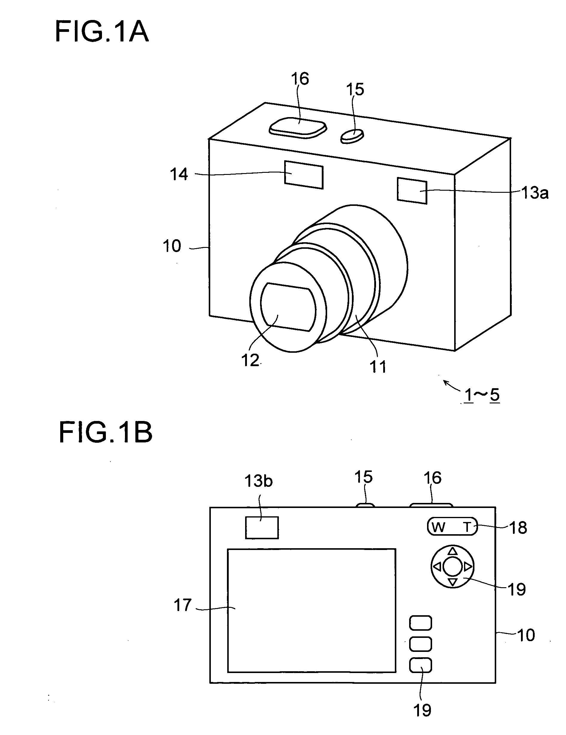
[0045] Hereinafter, embodiments of the present invention will be described with reference to the accompanying drawings. FIGS. 1A and 1B schematically show the external appearance of the digital camera 1 according to the invention. FIG. 1A is a perspective view showing the front and top faces of the digital camera. FIG. 1B is a back view. The digital camera 1 includes a main body 10 and a lens barrel 11 attached to the main body 10. The lens barrel 11 has a plurality of barrel components, and is movable back and forth so that it can project forward when photographing is performed and can be housed in the main body 10 when photographing is not performed. The lens barrel 11 houses and holds a taking optical system 12.

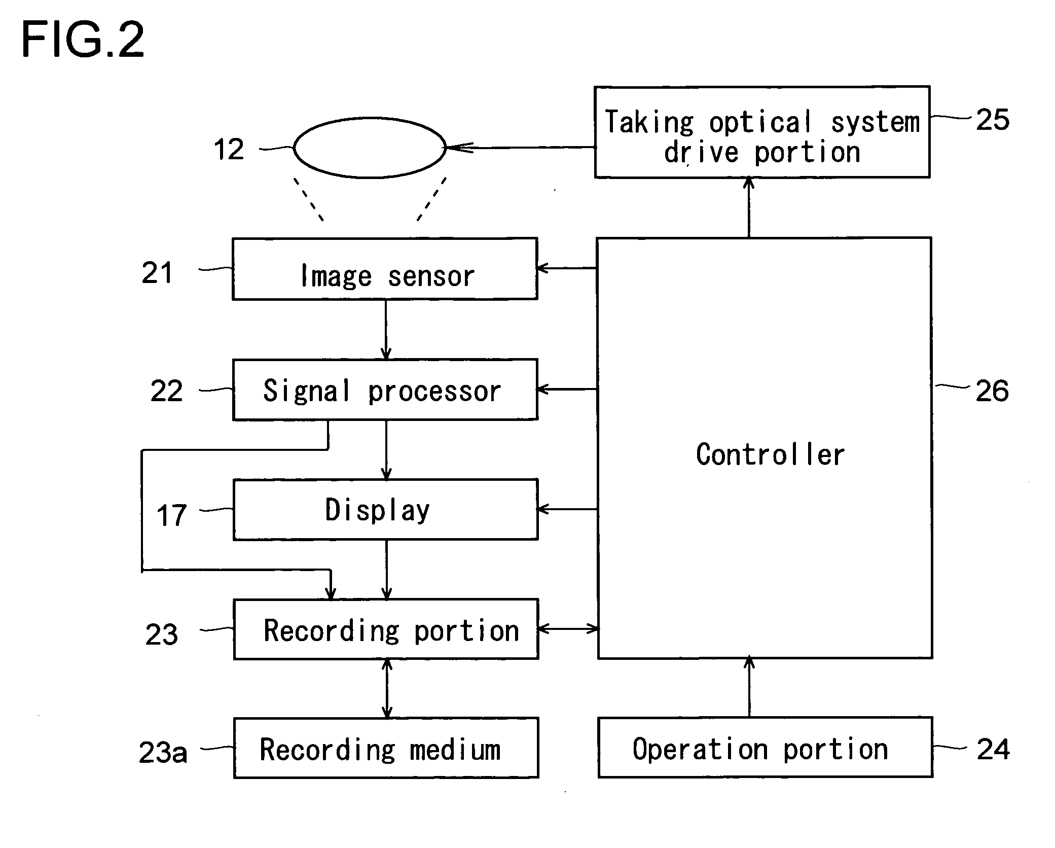
[0046] The taking optical system 12 directs the light coming from the subject to an image sensor 21 (see FIG. 2) housed in the main body 10 so as to image the light on the image sensor 21. The focal length of the taking optical system 12 is variable; that is, the taking op...

second embodiment

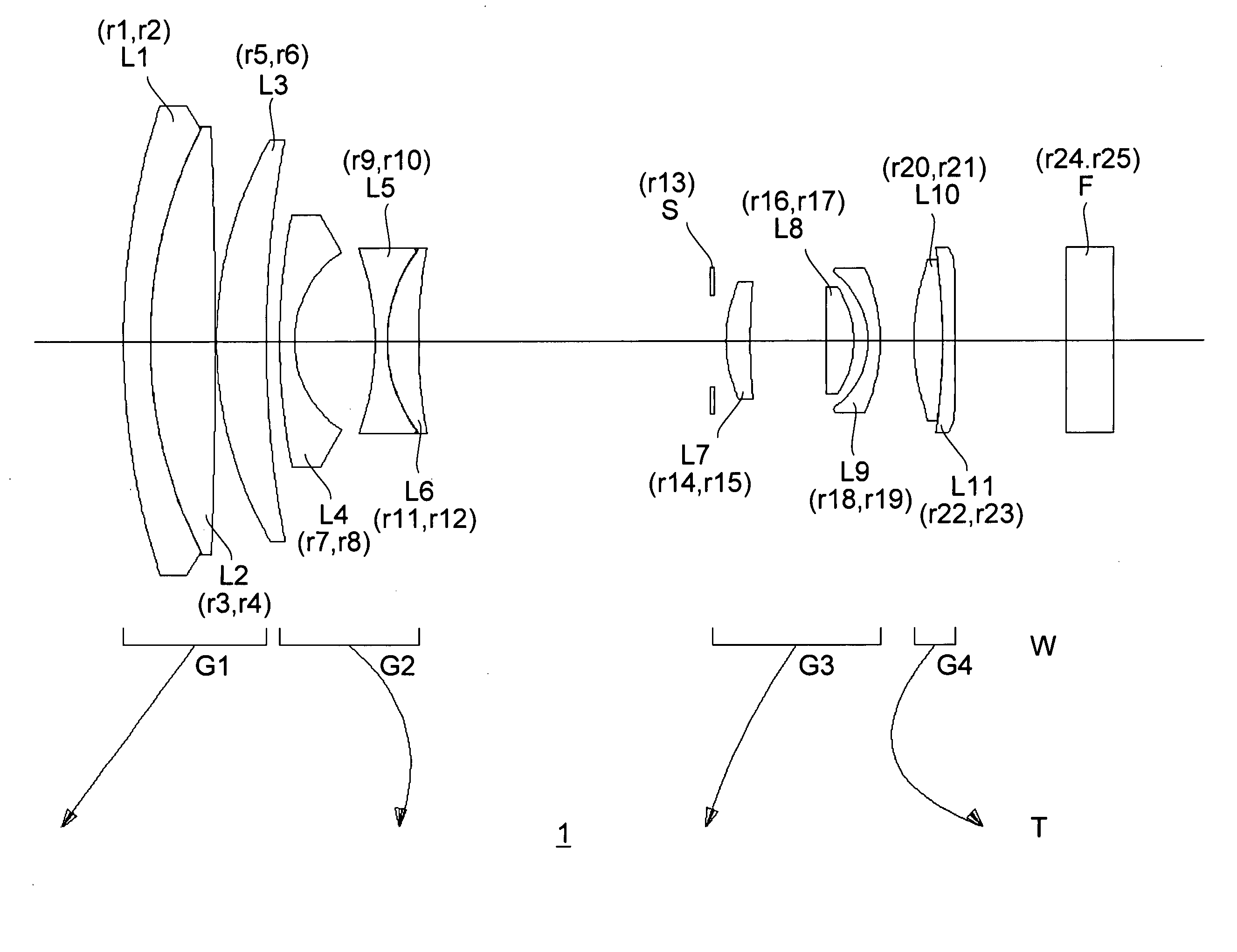
[0066]FIG. 5 shows the construction of the taking optical system 12 of the digital camera 2 of a The taking optical system 12 of the digital camera 2 includes, from the subject side, a first lens group G1, a second lens group G2, a third lens group G3, a forth lens group G4, and a fifth lens group G5.

[0067] The first lens group G1 is composed of three lens elements L1, L2, and L3, and has a positive optical power as a whole. The second lens group G2 is composed of three lens elements L4, L5, and L6, and has a negative optical power as a whole. The third lens group G3 is composed of four lens elements L7, L8, L9, and L10, and has a positive optical power as a whole. The forth lens group G4 is composed of two lens elements L11 and L12, and has a positive optical power as a whole. The fifth lens group G5 is composed of one lens element L13, and has a positive optical power.

[0068] Between the second lens group G2 and the third lens group G3 is disposed an aperture stop S. The aperture...

third embodiment

[0077]FIG. 7 shows the construction of the taking optical system 12 of the digital camera 3 of a The taking optical system 12 of the digital camera 3 includes, from the subject side, a first lens group G1, a second lens group G2, a third lens group G3, a forth lens group G4, and a fifth lens group G5.

[0078] The first lens group G1 is composed of three lens elements L1, L2, and L3, and has a positive optical power as a whole. The second lens group G2 is composed of three lens elements L4, L5, and L6, and has a negative optical power as a whole. The third lens group G3 is composed of four lens elements L7, L8, L9, and L10, and has a positive optical power as a whole. The forth lens group G4 is composed of two lens elements L11 and L12, and has a positive optical power as a whole. The fifth lens group G5 is composed of one lens element L13, and has a negative optical power.

[0079] Between the second lens group G2 and the third lens group G3 is disposed an aperture stop S. The aperture...


PUM


Abstract

The present invention provides a compact, high-performance, and easy-to-manufacture taking optical system that offers an extremely high zoom ratio. The taking optical system includes, from the subject side, a first lens group having a positive optical power, a second lens group having a negative optical power, a third lens group having a positive optical power, and a fourth lens group having a positive optical power. The taking optical system achieves zooming by the movements of the first to fourth lens groups and focusing by the movement of the fourth lens group. The taking optical system fulfills the following conditions: 0.05≦f3/f4≦0.95 and 7.0≦f1/fw≦20.0, where f1, f3, and f4 represent the focal lengths of the first, third, and fourth lens groups, respectively, and fw represents the focal length of the entire taking optical system at the wide-angle end thereof.

Description

[0001] This application is based on Japanese Patent Application No. 2004-367947 filed on Dec. 20, 2004, the contents of which are hereby incorporated by reference. BACKGROUND OF THE INVENTION [0002] 1. Field of the Invention [0003] The present invention relates to a taking optical system and an image sensing apparatus, and particularly to a taking optical system that offers a variable image sensing magnification and a high zoom ratio. [0004] 2. Description of Related Art [0005] As personal computers become widespread, digital cameras, which permit easy acquisition of images, have been becoming widespread in recent years. It is nowadays common to incorporate a digital camera into a data processing device such as a mobile computer, a cellular phone, or a personal digital assistant (PDA). Under these circumstances, increasingly compact digital still cameras are sought after, resulting in demands for further down-sizing of taking optical systems. [0006] On the other hand, in image senso...

Claims


Application Information

Patent Timeline
IPC IPC(8): G02B15/14
CPCG02B15/173G02B15/144113G02B15/145113
Inventor NAKATANI, TORUTERADA, MAMORUNABETA, KENSHI
Owner KONICA MINOLTA PHOTO IMAGING
Why Eureka
Try Eureka