Magnetic head with durability against static electricity

a static electricity and magnetic head technology, applied in the field of magnetic head, can solve the problems of large current generated to damage the read element, static electricity destruction, etc., and achieve the effect of improving static electricity durability, high yield and reliability

Inactive Publication Date: 2006-06-22
WESTERN DIGITAL TECH INC
View PDF1 Cites 4 Cited by
  • Summary
  • Abstract
  • Description
  • Claims
  • Application Information

AI Technical Summary

Benefits of technology

[0007] Although it is important to control an amount of a charge and a discharge time in a device susceptive to the static electricity, such as the GMR head (read element), any disclosure relating to such control has not been made. In order to further enhance durability against static electricity in the manufacture process, it is necessary also to improve control on the time the electric charge diffuses in addition to shunting between terminals and inserting a resistance or diode between terminals. When the charge diffuses in a short period of time, a large current is generated to damage the read element. In turn, when the charge diffuses for a long period of time, the charge is retained in a subsequent process to cause static electricity destruction. Hence, the present invention provides a read head which is implemented in a magnetic disk drive that supports a high recording density and a high transfer rate and is excellent in static electricity durability.
[0010] According to the present invention, it is possible to improve static electricity durability and to realize a magnetic head which is high in yield and reliability.

Problems solved by technology

When the charge diffuses in a short period of time, a large current is generated to damage the read element.
In turn, when the charge diffuses for a long period of time, the charge is retained in a subsequent process to cause static electricity destruction.

Method used


Image

  • Magnetic head with durability against static electricity
  • Magnetic head with durability against static electricity
  • Magnetic head with durability against static electricity

Examples


first embodiment

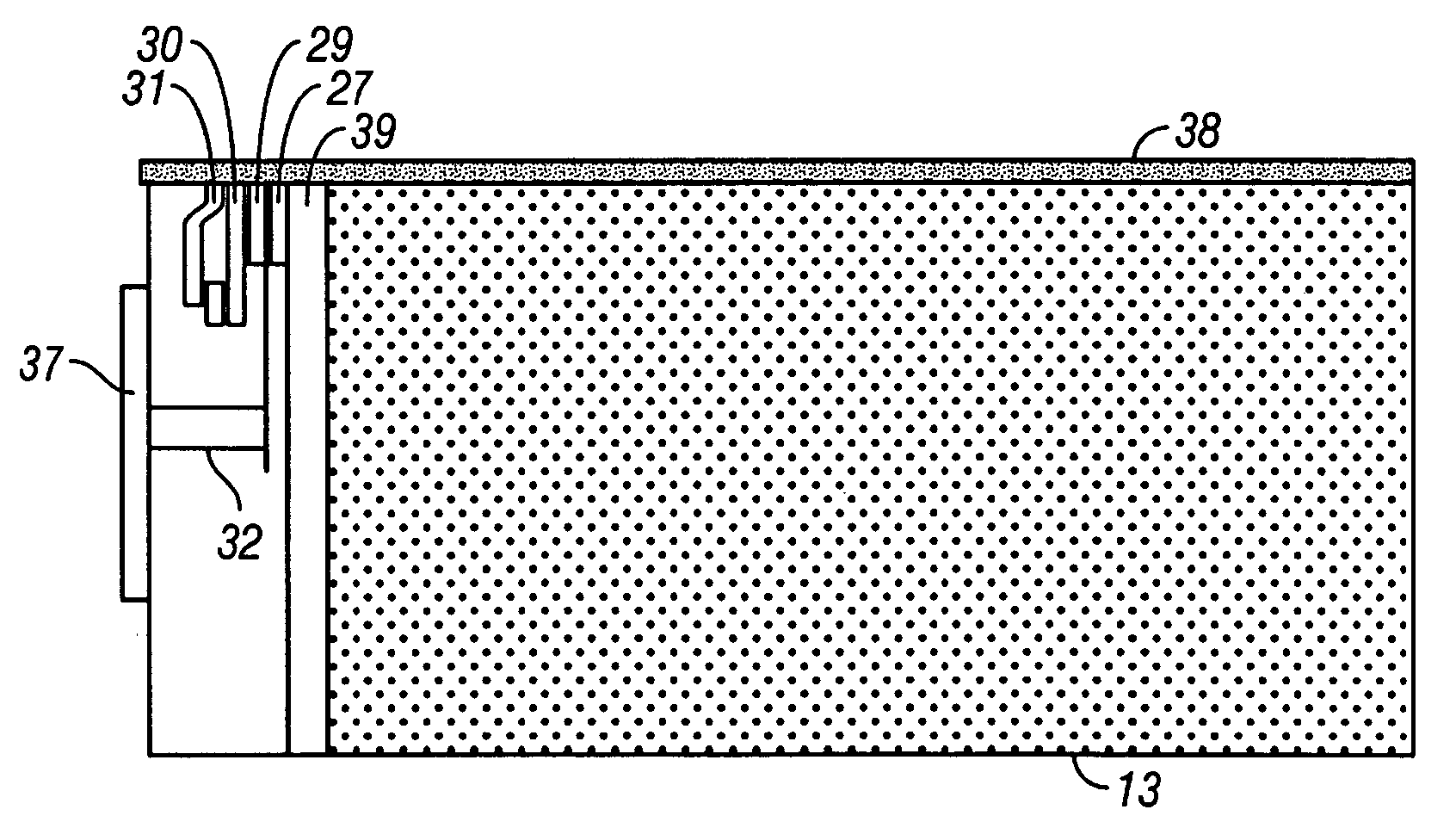
[0032]FIG. 12 shows a magnetic head according to the present invention. In this embodiment, a 1 nm-thick Si underlayer is formed and then a 2 nm-thick CAC carbon film is formed on the Si underlayer to obtain an ABS protection film 38. Further, a 0.7 nm-thick base alumina is formed, and a 3-μm thick lower magnetic shield 27 is formed. With the above constitution, a resistance value between a slider 13 and a read element terminal 37 becomes 1010 Ω, wherein a diffusion time becomes 10 ms.

second embodiment

[0033]FIG. 13 shows a magnetic head according to the present invention. In this embodiment, a dense film is formed under decreased gas pressure by changing a sputtering rate for a CAC carbon from 10−4 Torr to 10−5 Torr. A 1 nm-thick Si underlayer is formed and then a 2 nm-thick CAC carbon film is formed on the Si underlayer to obtain an ABS protection film 38. Further, a 0.7 nm-thick base alumina is formed, and a 3 μm-thick lower magnetic shield 27 is formed. With the above constitution, a resistance value between a slider 13 and a read element terminal 37 becomes 108 Ω, wherein a diffusion time becomes 1 ms.

[0034]FIG. 8 is a diagram showing a relationship between the base alumina film thickness and the resistance value. As is apparent from FIG. 8, it is possible to reduce the resistance value when the base alumina 39 of the magnetic heads shown in FIGS. 12 and 13 is decreased in thickness.

[0035]FIG. 9 is a diagram showing a relationship between the protection film thickness and th...


PUM

PropertyMeasurementUnit
time constantaaaaaaaaaa
resistanceaaaaaaaaaa
thicknessaaaaaaaaaa

Abstract

Embodiments of the invention provide a read head which is implemented in a magnetic disk drive that supports a high recording density and a high transfer rate and is excellent in static electricity durability. In one embodiment, a magnetic head wherein a charge diffuses from a read element to a slider at a time constant of about 100 ms or less.

Description

CROSS-REFERENCES TO RELATED APPLICATIONS [0001] This application claims priority from Japanese Patent Application No. JP2004-366052, filed Dec. 17, 2004, the entire disclosure of which is incorporated herein by reference. BACKGROUND OF THE INVENTION [0002] The present invention relates to a magnetic head having improved durability against static electricity and higher reliability. [0003] A spin valve element using the giant magnetoresistive effect has come into practical use as a read element of a magnetic disk drive. Read sensitivity has been improved along with improvements in recording density, with the result that damage caused by static electricity in the manufacture process gives rise to a problem. Waveform fluctuation and an increase in noise are generated by such damage in addition to electric breakdown and fusion of devices. This presents a major challenge from the standpoint of yields and reliability of magnetic heads. Hence, the following countermeasures have been taken a...

Claims


Application Information

Patent Timeline
Patent Type & Authority Applications(United States)
IPC IPC(8): G11B5/33G11B5/127
CPCG11B5/40
Inventor OHTSU, TAKAYOSHINATORI, SHOJI
Owner WESTERN DIGITAL TECH INC
Why Eureka
Try Eureka