
Belt for continuously variable transmission and manufacturing method of the same
- Summary
- Abstract
- Description
- Claims
- Application Information
AI Technical Summary
Benefits of technology
Problems solved by technology
Method used
Image

Examples
Embodiment Construction
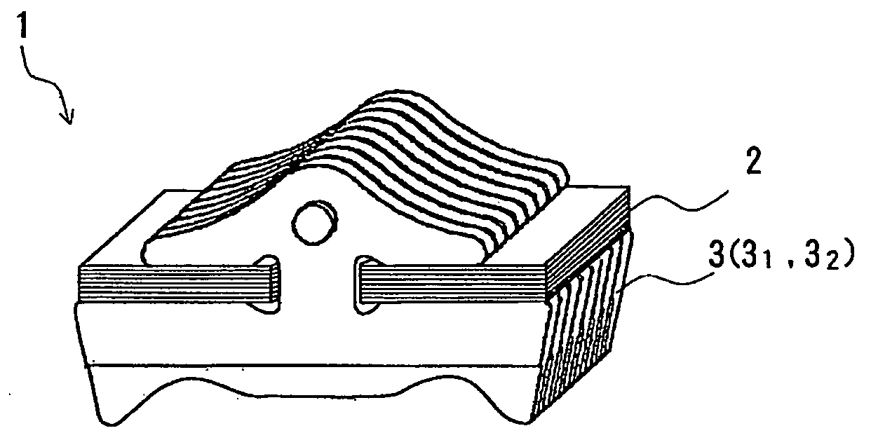
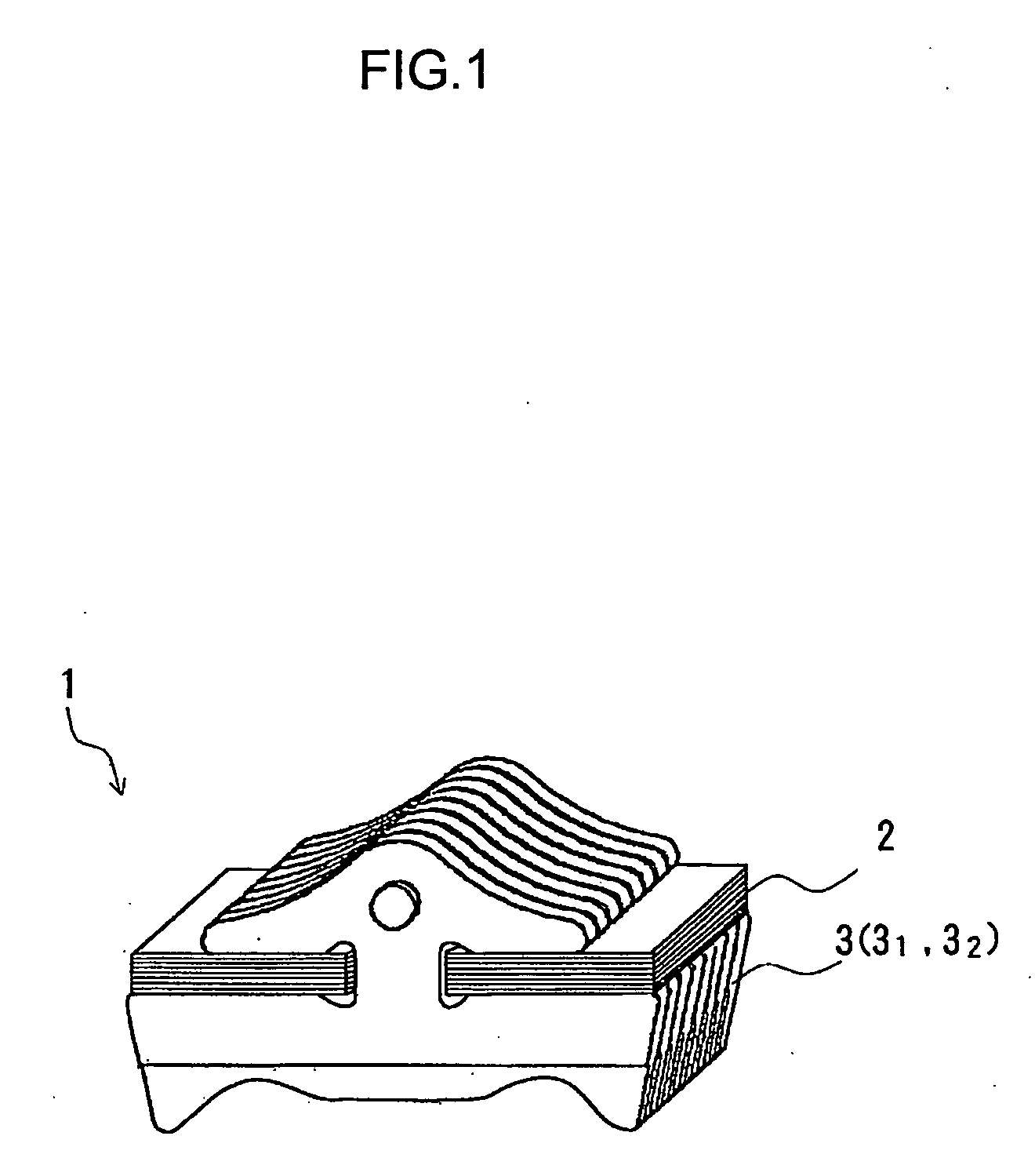
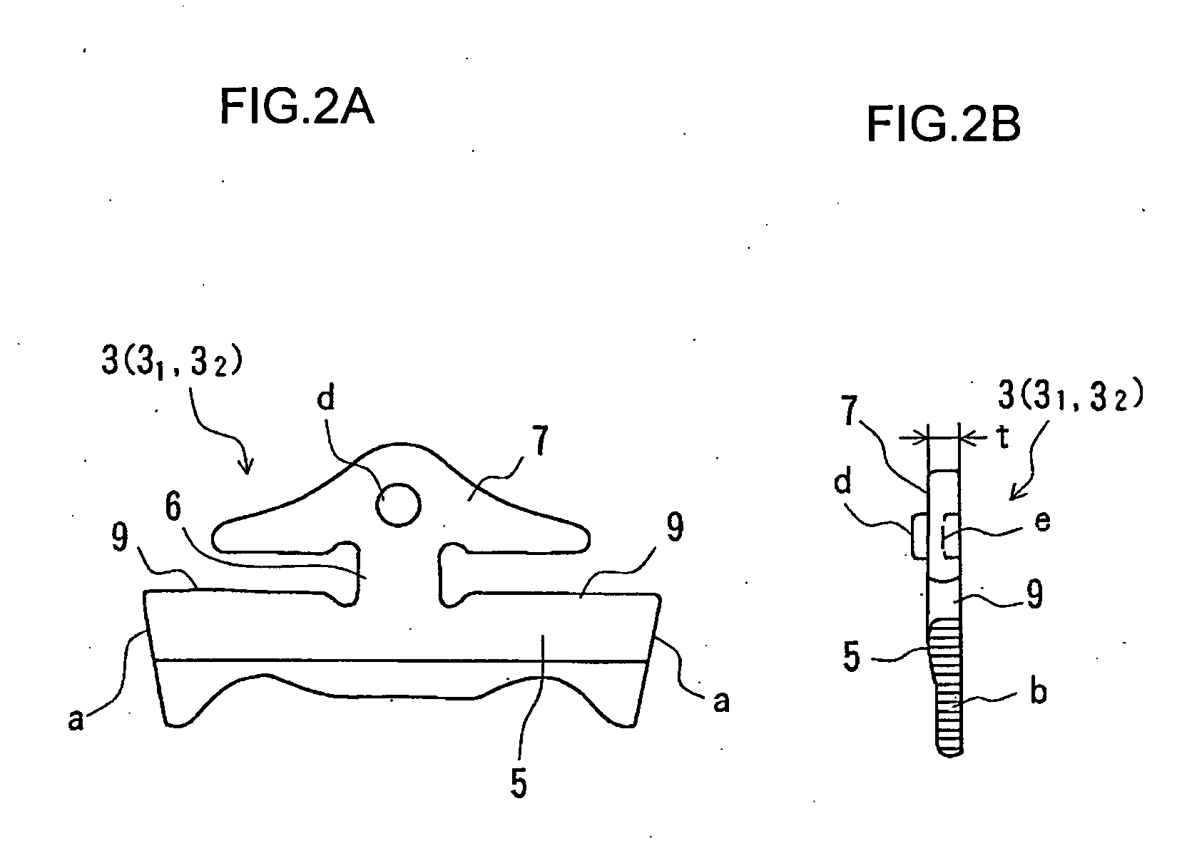
[0037] Exemplary modes for carrying out the invention will be explained below with reference to the accompanying drawings. FIG. 1 is a perspective view showing a part of a CVT belt and FIGS. 2A and 2B show a V block (element). The belt 1 is composed of a ring 2 in which a plurality of endless metal sheets are laminated and a large number of V blocks (elements) 3 are successively and endlessly attached to the ring 2. As shown in FIG. 2, in detail, the V block 3 is a plate made of steel, for example, and has a certain thickness. The V block has a body 5 with V-shaped right and left flanks a that abut against pulleys, and a head 7 linked with the body 5 via a pillar 6. A part between the body 5 and the head 7 on the right and left sides of the pillar 6 is a saddle 9 for receiving the ring 2. Channels b for flowing lubricant oil are formed on the right and left flanks a, and the head 7 is provided with a dimple d on one face thereof and with a hole e on the other face to maintain the at...
PUM
| Property | Measurement | Unit |
|---|---|---|
| Thickness | aaaaa | aaaaa |
| Ratio | aaaaa | aaaaa |
| Level | aaaaa | aaaaa |
Abstract
Description
Claims
Application Information