
Centrifugal separator with fluid injection openings formed in a separate strip insert

a separator and fluid injection technology, applied in centrifuges, rotary centrifuges, etc., can solve the problems of limiting the ability to tailor the arrangement to the best processing parameters, the device has not achieved commercial success, and the disclosure of long time, so as to enhance the inter-stage feed acceleration, reduce turbulence, and enhance the effect of metallurgical performan

Active Publication Date: 2006-06-22
F L SMIDTH & CO AS
View PDF69 Cites 8 Cited by
  • Summary
  • Abstract
  • Description
  • Claims
  • Application Information

AI Technical Summary

Benefits of technology

[0010] It is one object of the present invention to provide an improved centrifugal separator of the above general type in which wear problems are reduced by providing a replaceable insert.
[0027] Preferably the recess insert member includes a layer of a material attached thereto at the surface which is of increased wear resistance relative to a main material from which the recess insert member is formed. In some cases however and in some designs a material may be available which can provide both the wear resistance and the flexibility so that the extrusion may be formed in one piece.
[0033] The side walls of the recesses are preferably v-shaped so as to converge toward one another. However this is not essential and many different shapes of the side walls of the recess can be provided. Thus the side walls and particularly the upper side wall may be curved or grooved with angular grooves to provide different effects on material tending to migrate from the recess over the upper wall. it will be appreciated that the fact that the recess is formed in a piece which is extruded longitudinally allows the cross sectional shape of the recess to be tailored to whatever shape is desired. This extrusion method provides much more flexibility of shape relative to the conventional one piece molding method which limits the shaping of the bowl and its recesses to shapes which can be pulled off the male mold.
[0035] In a second embodiment described in more detail hereinafter, which is used with a bowl already having molded recesses, the insert portion has a portion which inserts into the recess and a face portion including a side portion located radially inwardly of a rib on a respective side of the recess and at least partly covering the rib so as to prevent the slurry from contacting the rib and causing wear to the rib. However the face portion may be shaped so that it reduces the contact of the slurry on the rib without actually covering the rib, particularly if it projects into the bowl to a height above the rib.
[0039] Preferably the side portion has an edge at an axial end thereof and an edge surface extending from the edge to the next adjacent recess and wherein the edge surface is substantially contiguous with the side wall of the next adjacent recess. Thus the side portion covers the whole of the rib and an end face of the rib. However the side portion may not in some examples cover the whole of the rib provided the side portion is shaped to reduce or prevent the impact of the slurry on the rib sufficiently to avoid wear of the rib and to concentrate the wear in the replaceable insert member.
[0065] 3) In addition to the additional extrusion profiles shown hereinafter, this system also allows the flexibility to provide a wide range of other inner face profiles on the extrusion for the purpose of enhancing inter-stage feed acceleration (inter-stage being from one fluidized ring to the next), inter-stage feed preparation (by introducing or reducing turbulence between the fluidized rings as desired), thereby enhancing metallurgical performance which can be customized on a case by case basis.

Problems solved by technology

This provides requirements on the construction and location of the holes which can lead to blockage and can limit the ability to tailor the arrangements to the best processing parameters.
This device has not achieved commercial success and the disclosure has been long abandoned as a workable arrangement.
Machines of this type have grown bigger and the tonnage capacities have increased which has lead to an increase in the associated wear problems.

Method used


Image

  • Centrifugal separator with fluid injection openings formed in a separate strip insert
  • Centrifugal separator with fluid injection openings formed in a separate strip insert
  • Centrifugal separator with fluid injection openings formed in a separate strip insert

Examples


Embodiment Construction

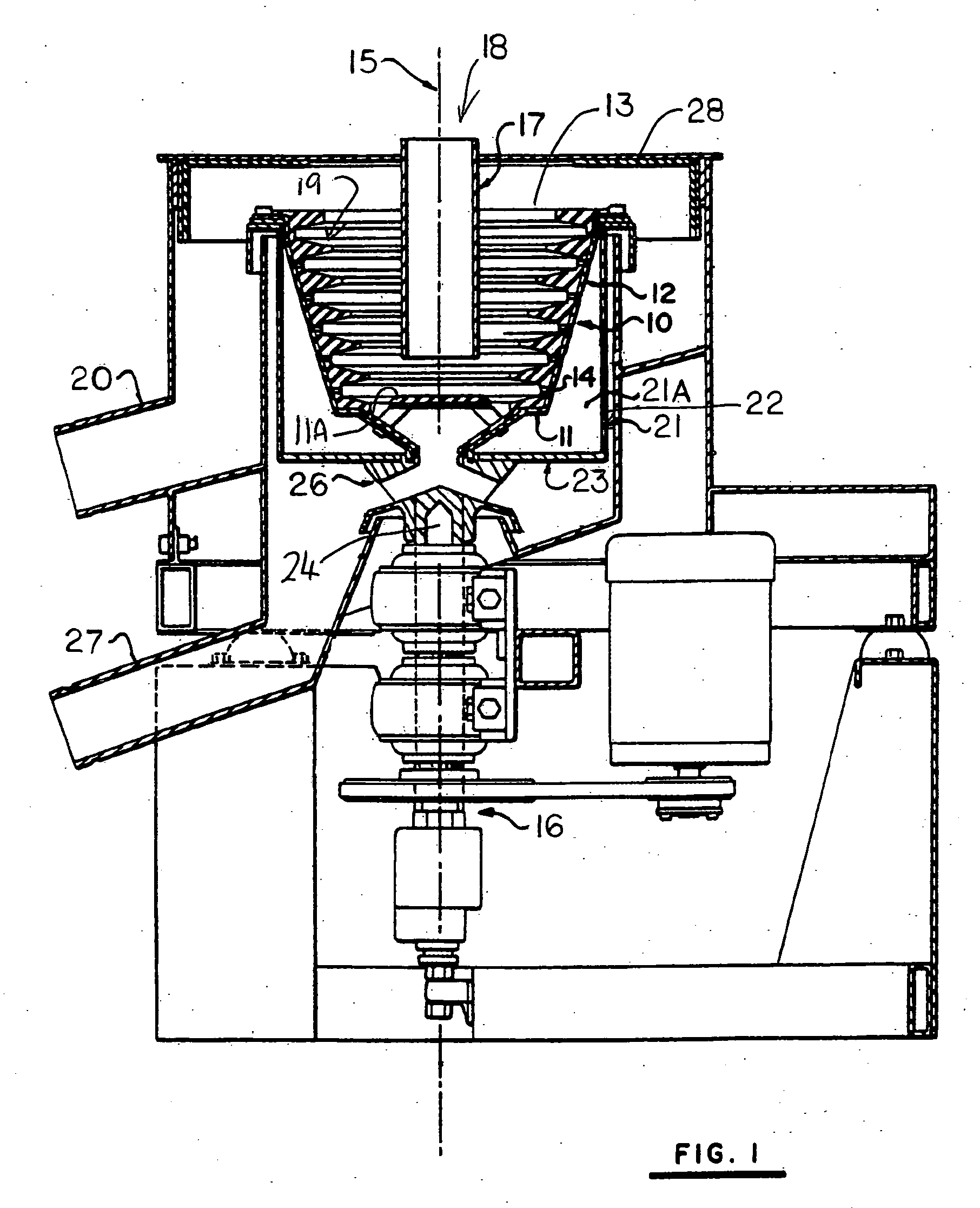
[0078] The general arrangement of the centrifugal separator shown in FIG. 1 is taken from the above U.S. Pat. No. 5,222,933 of the present inventor and therefore will described only briefly in regard to the points of importance. The disclosure of the above patents of the present assignee may be referred to for further details which may be necessary for a full understanding.

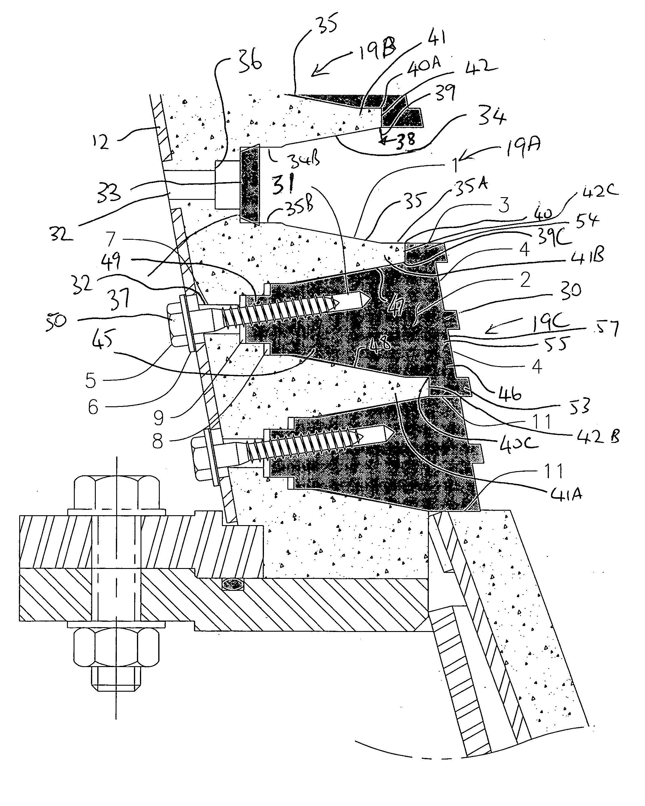
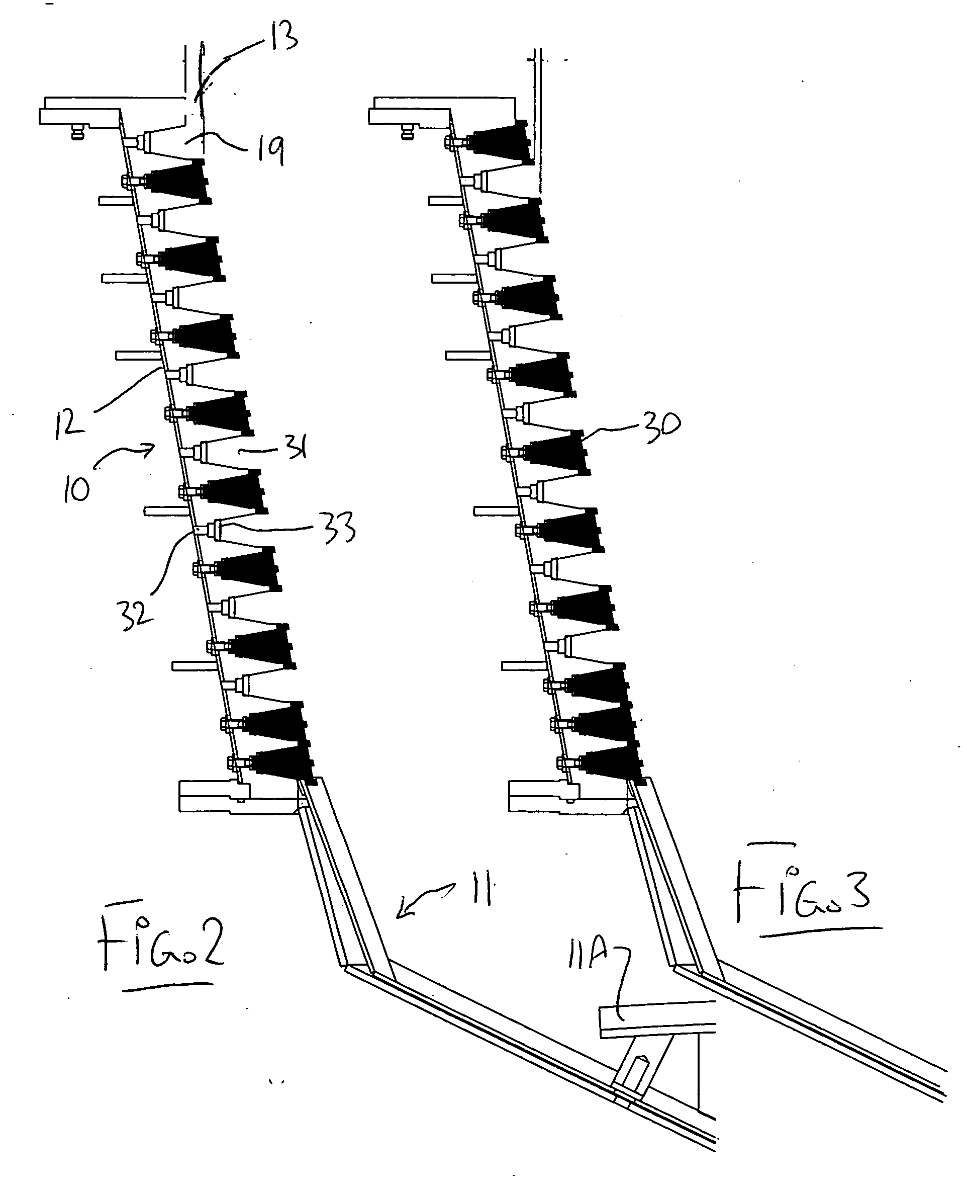
[0079] The apparatus therefore comprising a bowl generally indicated at 10 having a base generally indicated at 11 and a peripheral wall 12 standing upwardly from the base to an open mouth 13. The bowl can rotate around an axis 15 on a support shaft 16.

[0080] A feed duct 17 carries feed materials 18 in the form of a mixture of heavier and lighter particulate materials in a water slurry through the open mouth to a position adjacent to the base so the feed materials can be deposited onto a horizontal guide plate 11A at the base 11 and can move therefrom onto the peripheral wall 12 for separation of the heavier mat...


PUM


Abstract

A centrifuge concentrator bowl includes a plurality of fluidized recesses at axially spaced positions along the peripheral wall. Each recess is defined by two side walls which has water injection holes for fluidizing materials collecting in the recess. Some of the recesses are at least partly defined by a removable insert member arranged to be attached to a suitable mounting on the wall of the bowl. Each insert member includes a face portion defining a surface facing toward the axis of the bowl for engaging the slurry and preventing wear. The face portion may include a side portion on one side or both sides located radially inwardly of a rib on a respective side of the recess and at least partly covering the rib so as to prevent the slurry from contacting the rib and causing wear to the rib.

Description

[0001] This application claims priority under 35 U.S.C. 119 from Provisional Application 60 / 637,751 filed Dec. 22nd, 2004.[0002] This invention relates to a centrifugal separator of the type having a plurality of axially spaced annular recesses on a peripheral wall of a rotatable bowl. [0003] In U.S. Pat. Nos. 4,608,040, 4,776,833, 5,222,933, 5,421,806, 5,230,797 and 5,338,284 of Benjamin Knelson and now assigned to the present Assignee discloses a number of different arrangements of centrifugal separator of the type including a rotatable bowl having a peripheral wall of generally frusto-conical shape on which is provided a plurality of axially spaced, annular recesses. The particulate material containing fractions of different specific gravity to be separated is fed in slurry form through a feed duct to a position at or adjacent a base of the bowl so that the feed materials pass over the peripheral wall with heavier particulate materials collecting in the annular recesses while lig...

Claims


Application Information

Patent Timeline
Patent Type & Authority Applications(United States)
IPC IPC(8): B04B11/04
CPCB04B1/00B04B7/08B04B7/12B04B11/02B04B15/12
Inventor ZONNEVELD, EDWIN JOHN WILLIAMKNABE, KURTKNELSON, BRETT ROBERT HENRY
Owner F L SMIDTH & CO AS
Learn More