Vaso-occlusive device having pivotable coupling

a vasoocclusive device and pivoting technology, applied in the field of assembly for implanting vasoocclusive devices, can solve the problem of unsatisfactory extension of the duration of the procedur

Inactive Publication Date: 2006-06-22
STRYKER EURO OPERATIONS HLDG LLC +1
View PDF27 Cites 133 Cited by
  • Summary
  • Abstract
  • Description
  • Claims
  • Application Information

AI Technical Summary

Benefits of technology

[0012] In accordance with another aspect of the invention, a method of occluding a vascular site (e.g., an aneurysm) using the vaso-occlusive assembly is provided. The method comprises manipulating the pusher member to place the vaso-occlusive member adjacent the vascular site. If the vascular site is an aneurysm, the delivery catheter can be placed within the aneurysmal neck, and the pusher member can be manipulated to place the vaso-occlusive member within the aneurysmal sac. The method furt

Problems solved by technology

Having the catheter tip displaced from the aneurysm requires the physician to relocate the catheter tip p

Method used


Image

  • Vaso-occlusive device having pivotable coupling
  • Vaso-occlusive device having pivotable coupling
  • Vaso-occlusive device having pivotable coupling

Examples


Embodiment Construction

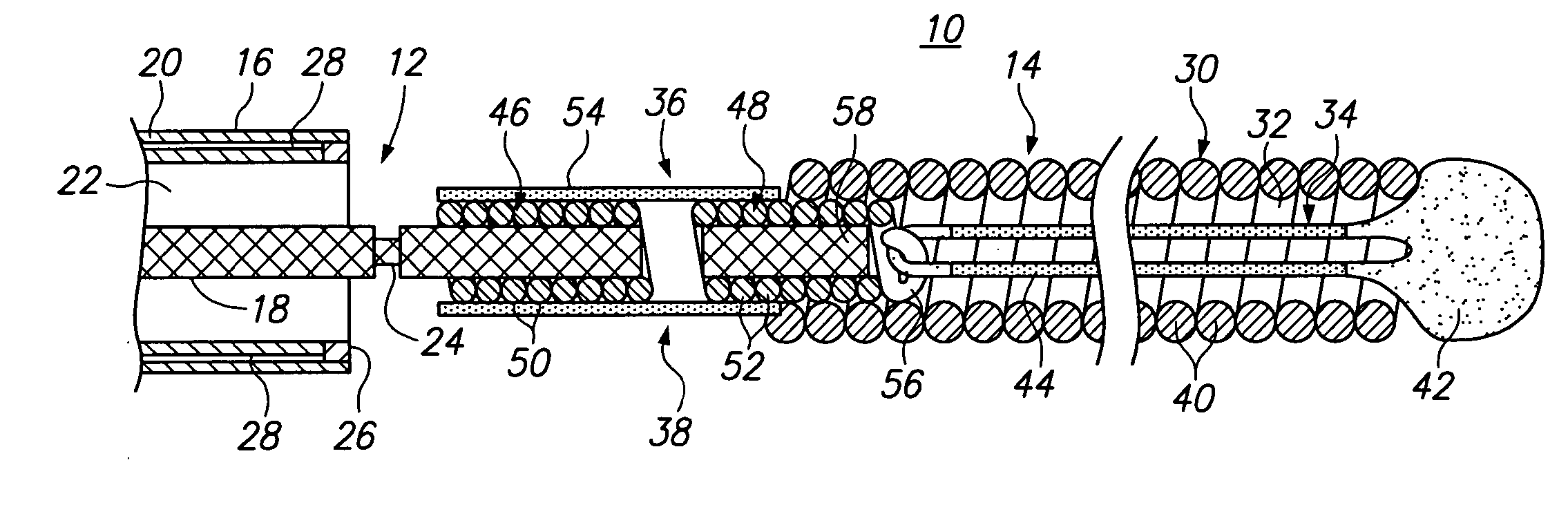
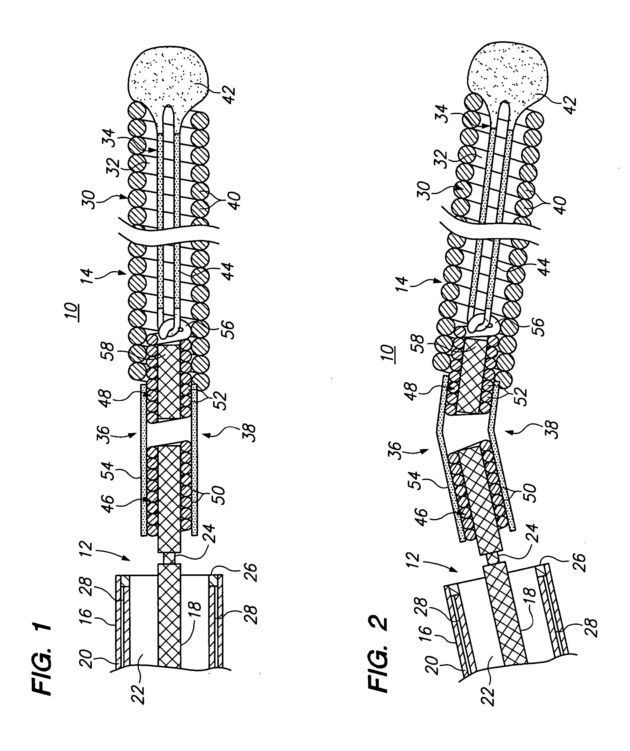
[0027] Referring to FIG. 1, a vaso-occlusive assembly 10 constructed in accordance with a preferred embodiment is illustrated. For purposes of orientation, the term “proximal“as it qualifies an element generally refers to the left end of the element, and the term “right” as it refers to an element generally refers to the right end of the element, as shown in the figures. The vaso-occlusive assembly 10 generally comprises a delivery device 12, which includes an elongated tubular catheter 16 and a pusher member 18, and a vaso-occlusive device 14 detachably associated with the distal end of the delivery device 12, and in particular, the distal end of the pusher member 18.

[0028] The catheter 16 comprises an elongated tubular member 20 having a delivery lumen 22 in which the pusher member 18, and thus, the vaso-occlusive device 14, is slidably disposed. The tubular member 20 can be composed of any suitable flexible and biocompatible material that allows it to be introduced through the t...


PUM


Abstract

An assembly for occluding a vascular site (e.g., an aneurysm) of a human or veterinary patient includes a vaso-occlusive member, a pusher member having a distal end and a severable junction located proximal to the distal end, and a pivotable coupling that couples the pusher member to the occlusive member. A delivery catheter can be used to deliver the vaso-occlusive member to the vascular site. A method of using the assembly to occlude an aneurysm having an aneurysmal sac and an aneurysmal neck, comprises locating the catheter within the aneurysmal neck, and manipulating the pusher member to place the vaso-occlusive member within the aneurysmal sac. The method further comprises severing the severable junction to detach the vaso-occlusive member from the pusher member. As a result, an axial force is applied by the vaso-occlusive member in a proximal direction, which buckles the pivotable coupling to laterally deflect the axial force. The lateral deflection of the axial force caused by the buckling of the pivotable coupling prevents the catheter from being displaced from the aneurysmal neck by the axial force.

Description

FIELD OF THE INVENTION [0001] The present invention relates to assemblies for implanting vaso-occlusive devices in-vivo for establishing an embolus or vascular occlusion in a vessel of a human or veterinary patient. BACKGROUND OF THE INVENTION [0002] Vaso-occlusive devices or implants are used for a wide variety of reasons. They are often used for treatment of intra-vascular aneurysms. This is to say that the treatment involves the placement of a vaso-occlusive device in an aneurysm to cause the formation of a clot and eventually of a collagenous mass containing the vaso-occlusive device. These occlusions seal and fill the aneurysm thereby preventing the weakened wall of the aneurysm from being exposed to the pulsing blood pressure of the open vascular lumen. Treatment of aneurysms in this fashion is a significant improvement over the surgical method typically involved. [0003] A common vaso-occlusive device is a soft, helically wound coil. A typical commercial coil will be formed by...

Claims


Application Information

Patent Timeline
IPC IPC(8): A61M29/00
CPCA61B17/12113A61B17/12145A61B17/12154A61B2017/00477A61B2017/12063A61B2017/12095A61B17/12022A61B2017/12054
Inventor WALLACE, MICHAEL P.RAMZIPOOR, KAMAL
Owner STRYKER EURO OPERATIONS HLDG LLC
Why Eureka
Try Eureka