Cardiovascular valve assembly

a technology of valve assembly and valve valve, which is applied in the field of cardiac valve assembly, can solve the problems of affecting the operative survival achieving the effects of reducing the risk of operative complications, and improving the operative survival rate of patients after valve replacement surgery

Inactive Publication Date: 2006-06-22
VALVEXCHANGE
View PDF74 Cites 93 Cited by
  • Summary
  • Abstract
  • Description
  • Claims
  • Application Information

AI Technical Summary

Benefits of technology

[0007] An advantage of the present invention is the provision of a cardiovascular valve assembly including a replaceable valve member and a base member, wherein the replaceable valve member is conveniently attachable to and detachable from the base member that can be permanently installed in a patient.
[0008] Still another advantage of the present invention is the provision of a cardiovascular valve assembly that comprises a replaceable valve member including a valve frame that is sufficiently elastic to allow expansion and collapse thereof.
[0009] Yet another advantage of the present invention is the provision of a cardiovascular valve assembly including a replaceable valve member having a mounting assembly that can be gripped by snares.
[0010] These and other advantages will become apparent from the following description of a preferred embodiment taken together with the accompanying drawings and the appended claims.

Problems solved by technology

This process can take several hours and subjects the patient to significant operative mortality.
While operative mortality during a first valve replacement surgery can be very low, subsequent valve replacement surgeries have increased operative mortality.
However, since many typical cardiovascular valves have a lifespan of about 10 years, it often becomes necessary to replace cardiovascular valves one or more times.
Thus far, this goal has been extremely difficult to reach.

Method used


Image

  • Cardiovascular valve assembly
  • Cardiovascular valve assembly
  • Cardiovascular valve assembly

Examples


Embodiment Construction

[0033] The present invention provides improvement to the devices disclosed in U.S. Pat. No. 6,530,952 entitled “Bioprosthetic Cardiovascular Valve System” (issued Mar. 11, 2003) and U.S. Pat. No. 6,569,196 entitled “System for Minimally Invasive Insertion of a Bioprosthetic Heart Valve” (issued May 27, 2003), both of which are fully incorporated herein by reference. Disclosed herein are various embodiments of the present invention. It should be understood that the present invention may be practiced using a combination of features from the various embodiments disclosed herein. In the drawings, similar components of the various embodiments will bear the same reference numbers.

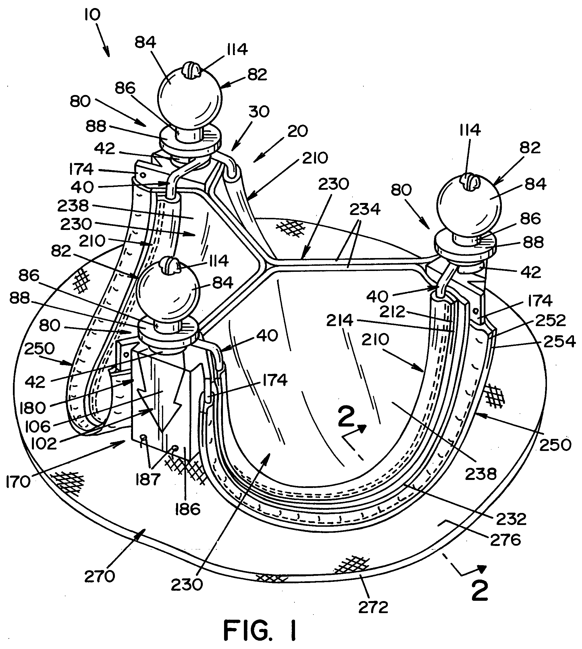
[0034] Referring now to the drawings wherein the showings are for the purposes of illustrating embodiments of the present invention only and not for the purposes of limiting same, FIG. 1 illustrates a cardiovascular valve assembly 10 according to one embodiment of the present invention. Cardiovascular valve asse...


PUM


Abstract

A cardiovascular valve assembly comprising a base member that is affixed to a patient using conventional sutures or staples, and a replaceable valve member including a valve frame that supports a plurality of valve leaflets. The valve member mates with the base member, and can be detached from the base member for convenient replacement.

Description

RELATED APPLICATIONS [0001] This application claims the benefit of U.S. Provisional Application No. 60 / 636,608, filed Dec. 16, 2004, which is hereby fully incorporated herein by reference.FIELD OF THE INVENTION [0002] The present invention relates generally to a cardiovascular valve assembly, and more specifically relates to a cardiovascular valve assembly comprised of a base member that remains in a patient, and a valve member that is detachably mountable to the base member. BACKGROUND OF THE INVENTION [0003] The current practice of inserting a bioprosthetic cardiovascular valve involves cutting a patient's chest open, placing the patient on cardiopulmonary bypass, and surgically inserting the valve into an aorta. This process can take several hours and subjects the patient to significant operative mortality. While operative mortality during a first valve replacement surgery can be very low, subsequent valve replacement surgeries have increased operative mortality. Consequently, fi...

Claims


Application Information

Patent Timeline
Patent Type & Authority Applications(United States)
IPC IPC(8): A61F2/24
CPCA61F2/2412A61F2/2409A61F2250/006A61F2002/9528A61F2/243
Inventor VESELY, IVAN
Owner VALVEXCHANGE
Why Eureka
Try Eureka