Rough road detection

a technology for detecting and responding to rough roads, applied in mechanical measuring arrangements, external condition input parameters, special data processing applications, etc., can solve problems such as torque disturbance, increase belt wear, and adverse effects

Inactive Publication Date: 2006-06-22
GM GLOBAL TECH OPERATIONS LLC
View PDF29 Cites 45 Cited by
  • Summary
  • Abstract
  • Description
  • Claims
  • Application Information

AI Technical Summary

Benefits of technology

[0006] In still other features, an acceleration calculator reduces vertical acceleration data from the first and second acceleration sensors to a single computed acceleration value. The limit comparison module determines the computed acceleration value is within the acceleration limits if the computed acceleration value is greater than the lower bound and less than the upper bound. The adaptive acceleration limits module selects the first and second acceleration limits from an acceleration limits table based upon the speed of the vehicle. The computed acceleration value is either of the measured vertical acceleration of the front left wheel and the measured vertical acceleration of the front right wheel, whichever has the greater absolute value.
[0007] A road condition aware system for a vehicle comprises the rough road detection system and further comprises a continuously variable transmission (CVT) that includes a be

Problems solved by technology

When a vehicle travels over rough road, vibration is transmitted through wheels of the vehicle, possibly producing adverse effects.
For example, the vibration may cause a belt of a continuously variable transmission (CVT) to slip, which increases belt wear and introduces torque disturbances.
Variations in wheel speed caused by the rough road can also stre

Method used


Image

  • Rough road detection
  • Rough road detection
  • Rough road detection

Examples


Embodiment Construction

[0019] The following description of the preferred embodiments is merely exemplary in nature and is in no way intended to limit the invention, its application, or uses. For purposes of clarity, the same reference numbers will be used in the drawings to identify similar elements. As used herein, the term module refers to an application specific integrated circuit (ASIC), an electronic circuit, a processor (shared, dedicated, or group) and memory that execute one or more software or firmware programs, a combinational logic circuit, and / or other suitable components that provide the described functionality.

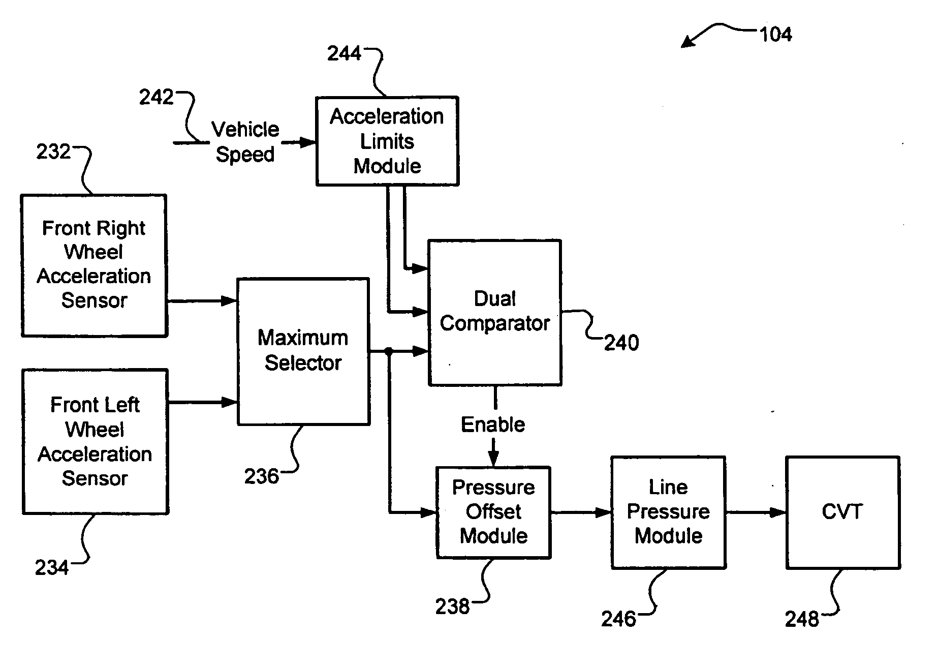
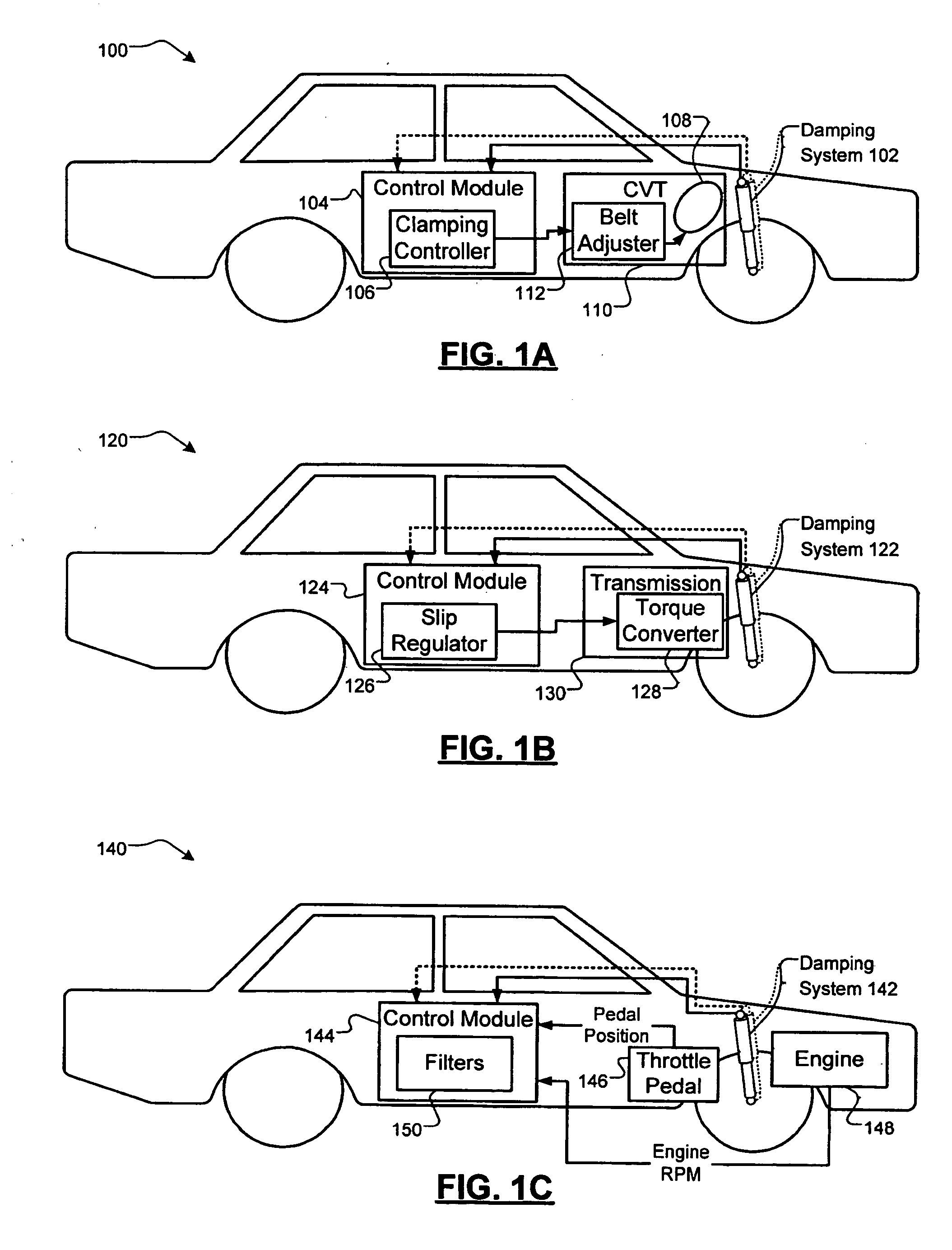
[0020] Referring now to FIG. 1A, a vehicle 100 including an exemplary road condition aware control module 104 that adjusts a belt 108 of a continuously variable transmission (CVT) 110 is depicted. A damping system 102 controls the interface between a frame and wheels of the vehicle, which determines how the vehicle reacts to imperfections in a road surface. The damping system 102 incl...


PUM


Abstract

A rough road detection system for a vehicle comprises a first acceleration sensor that measures vertical acceleration of a component of the vehicle. An adaptive acceleration limits module determines a first acceleration limit based upon a speed of the vehicle. A limit comparison module generates a rough road signal based on a comparison of the first acceleration limit from the adaptive acceleration limits module and the measured acceleration from the first acceleration sensor.

Description

FIELD OF THE INVENTION [0001] The present invention relates to systems for detecting and responding to rough road signals in a vehicle. BACKGROUND OF THE INVENTION [0002] When a vehicle travels over rough road, vibration is transmitted through wheels of the vehicle, possibly producing adverse effects. For example, the vibration may cause a belt of a continuously variable transmission (CVT) to slip, which increases belt wear and introduces torque disturbances. [0003] Variations in wheel speed caused by the rough road can also stress other engine and drivetrain components. Outputs generated by engine speed (revolutions per minute) and throttle pedal position sensors may also be impacted by the vibration from the rough road. For example, bouncing of the vehicle caused by rough road may cause the driver's foot to bounce on the accelerator pedal in a constructive interference pattern. SUMMARY OF THE INVENTION [0004] A rough road detection system for a vehicle comprises a first accelerati...

Claims


Application Information

Patent Timeline
IPC IPC(8): G06F19/00
CPCB60W2550/147F16H59/66F16H61/14F16H61/66272Y10T477/75Y10T477/635Y10T477/69367Y10T477/619Y10T477/624B60W2552/35
Inventor ROBERT, DOMINIQUESCELERS, HERVETISSOT, PASCAL
Owner GM GLOBAL TECH OPERATIONS LLC
Why Eureka
Try Eureka