Substrate treating apparatus

a technology for treating apparatus and substrates, applied in the direction of cleaning using liquids, instruments, coatings, etc., can solve the problems of increasing the installation space, increasing the cost, and sometimes showing unsatisfactory results or quality of treatment of substrates, so as to avoid the effect of increasing the footprin

Inactive Publication Date: 2006-06-29
DAINIPPON SCREEN MTG CO LTD
View PDF13 Cites 51 Cited by
  • Summary
  • Abstract
  • Description
  • Claims
  • Application Information

AI Technical Summary

Benefits of technology

[0075] The second table may comprise a plurality of tables arranged vertically. The plurality of second tables allow an increased number of substrates to be transported between the storage block and second treating block. Since the second tables are arranged vertically, an increase in footprint is avoided.
[0076] The apparatus according to this invention may further comprise a first partition separating the storage block from the first treating block, and defining a first passage opening opposed to the receptacles placed on the first table for allowing passage of the substrates; a first shutter member for opening and closing the first passage opening; a second partition separating the storage block from the second treating block, and defining a second passage opening opposed to the receptacles placed on the second table for allowing passage of the substrates; and a second shutter member for opening and closing the second passage opening; the first transport mechanism being arranged to load and unload the substrates en bloc into / from the receptacles on the first table through the first passage opening; the second transport mechanism being arranged to load and unload the substrates one at a time into / from the receptacles on the second table through the second passage opening. The first and second partitions and first and shutter members prevent the atmosphere of the storage block flowing into the first and second treating blocks. Thus, in the first and second treating blocks which receive the substrates from the receptacles, the substrates are never contaminated by the atmosphere from the storage block.
[0077] Each of the receptacles may have an opening formed in one side thereof, and include a lid for closing the opening; the first shutter member having a first attaching / detaching and holding mechanism for attaching, detaching and holding the lid; the second shutter member having a second attaching / detaching and holding mechanism for attaching, detaching and holding the lid. With the first and second attaching / detaching and holding mechanisms provided, the lids of the receptacles are detachable by the first and second shutter members which open and close the first and second passage openings. Thus, the interiors of the receptacles are opened only to the first and second treating blocks. Since the atmosphere of the storage block accommodating the receptacles does not flow into the receptacles, the substrates in the receptacles are free from contamination.

Problems solved by technology

With the batch treating mode, substrates sometimes show unsatisfactory results or quality of treatment.
This results in inconveniences of enlarged installation space and an increase in cost.
Moreover, when transporting substrates between these substrate treating apparatus, the substrates once move outside one of the apparatus, thus facing a possibility of being contaminated.

Method used


Image

  • Substrate treating apparatus
  • Substrate treating apparatus
  • Substrate treating apparatus

Examples


embodiment 1

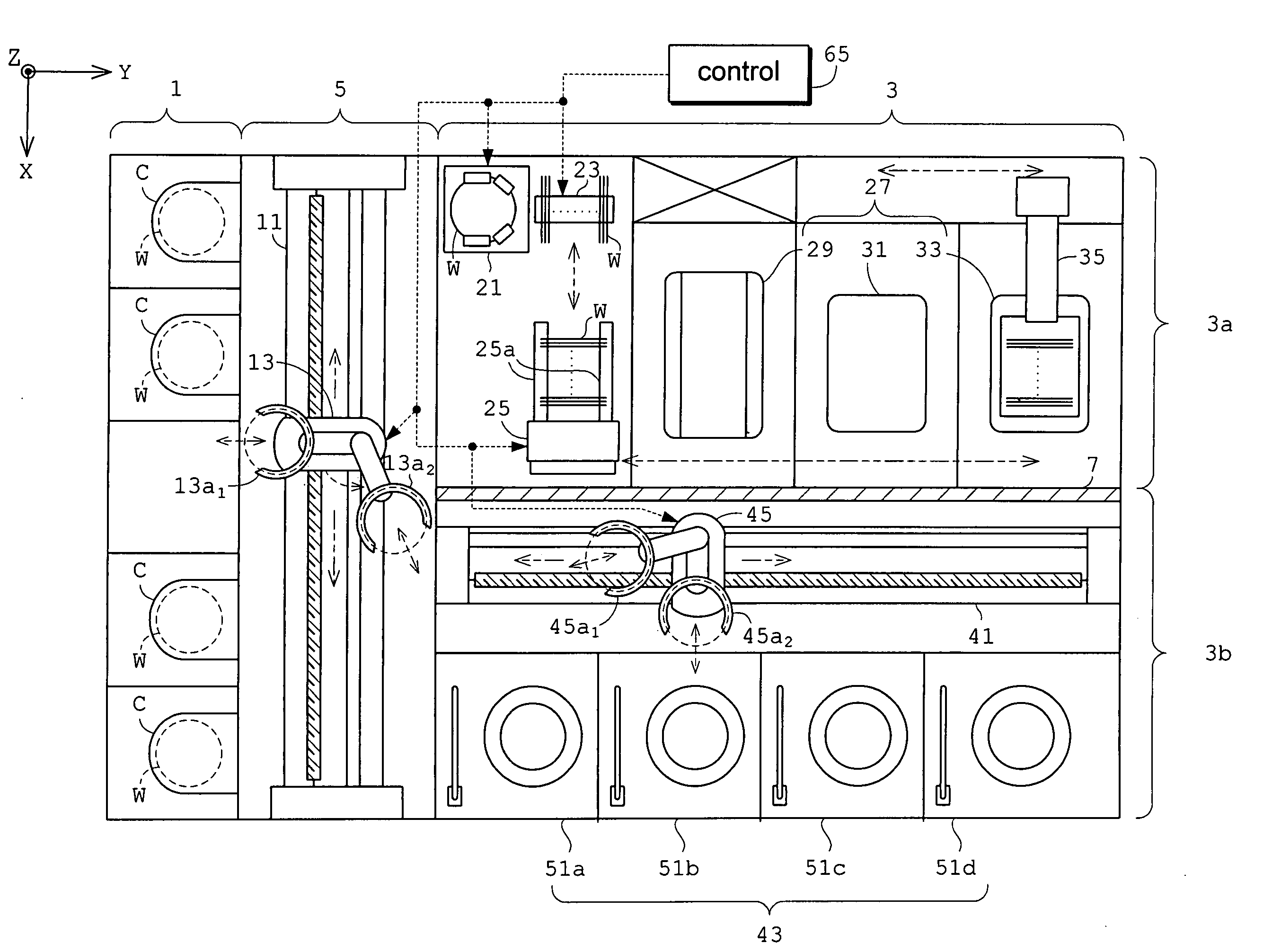
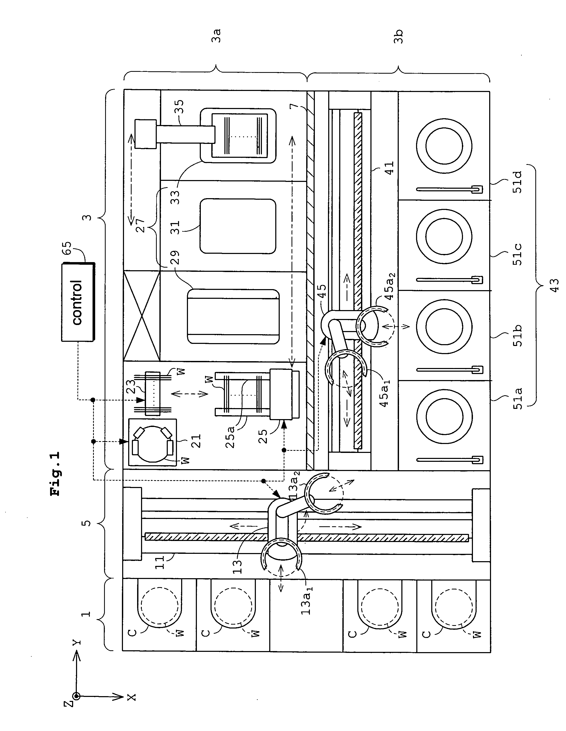
[0137]FIG. 1 is a plan view showing an outline of a substrate treating apparatus in Embodiment 1.

[0138] The substrate treating apparatus is constructed for performing a predetermined treatment (e.g. resist stripping treatment) of substrates or wafers W (e.g. semiconductor wafers). The apparatus, broadly, includes a cassette table 1 for supporting cassettes C storing wafers W, a treating block 3 for performing the predetermined treatment of wafers W, and a transport block 5 disposed between the cassette table 1 and treating block 3 for transporting the wafers W therebetween. The treating block 3 has a first treating section 3a for treating a plurality of wafers W en bloc, and a second treating section 3b for treating the wafer W one at a time.

[0139] Each cassette C placed on the cassette table 1 contains a plurality of (e.g. 25) wafers W in horizontal posture and in multiple stages (which wafers W may be called hereinafter “group of wafers W” where appropriate).

[0140] The transpor...

embodiment 2

[0196] Embodiment 2 of this invention will be described next.

[0197]FIG. 9 is a plan view showing an outline of a substrate treating apparatus in Embodiment 2. Like reference numerals are used to identify like parts which are the same as in Embodiment 1 and will not be described again.

[0198] The substrate treating apparatus in Embodiment 2, broadly, includes a cassette table 1, a treating block 3, a transport block 5 and an auxiliary transport block 9. The auxiliary transport block 9 is disposed opposite the transport block 5 across the treating block 3.

[0199] The auxiliary transport block 9 has, arranged therein, a second posture changer 61 for delivering and receiving wafers W to / from the second treating section's transport mechanism 45, and changing the posture of a group of wafers W en bloc between horizontal posture and vertical posture, and a second pusher 63 for delivering and receiving the group of wafers W to / from a first treating section's transport mechanism 26 having a...

embodiment 3

[0220] Embodiment 3 of this invention will be described next with reference to the drawings.

[0221]FIG. 10 is a plan view showing an outline of a substrate treating apparatus in Embodiment 3.

[0222] The substrate treating apparatus in Embodiment 3 is designed for cleaning, etching and drying wafers W (e.g. semiconductor wafers), and includes a storage block 101 for receiving sealed receptacles (known as FOUPs (front opening unified pods, and referred to hereinafter as “foups”) F, each for storing a plurality of wafers W, a first treating block 103 for treating a plurality of wafers W en bloc, a second treating block 105 for treating wafers W one at a time, and a transport block 107 for transporting wafers W between the storage block 101, first treating block 103 and second treating block 105. Each foup F corresponds to the receptacle in this invention. The storage block 101, first treating block 103, second treating block 105 and transport block 107 correspond to the storage block, ...


PUM


Abstract

A substrate treating apparatus includes a storage block for accommodating foups each storing a plurality of substrates, a first treating block for treating a plurality of substrates en bloc, a second treating block for treating one substrate at a time, and a transport device for transporting the substrates between the foups, first treating block and second treating block. The substrates may be treated in a mode of treating a plurality of substrates en bloc, and/or a mode of treating one substrate at a time.

Description

BACKGROUND OF THE INVENTION [0001] (1) Field of the Invention [0002] This invention relates to a substrate treating apparatus for treating substrates such as semiconductor wafers, glass substrates for liquid crystal displays and the like (hereinafter called simply substrates). [0003] (2) Description of the Related Art [0004] For various types of substrate treating apparatus, treating modes may be classified broadly into a batch mode for treating a plurality of (e.g. 25) substrates en block, and a piecemeal mode for treating one substrate at a time. [0005] In the batch treating mode, a plurality of substrates under treatment are immersed en bloc in a treating solution stored in a treating tank. This mode has an excellent mass production feature of substrate treatment, and assures a uniform quality of substrate treatment (as disclosed in Japanese Unexamined Patent Publication No. 2001-196342, for example). [0006] In the piecemeal or single-substrate treating mode, a treating solution ...

Claims


Application Information

Patent Timeline
Patent Type & Authority Applications(United States)
IPC IPC(8): B08B3/00B05C11/00
CPCG03F7/7075H01L21/67028H01L21/67173H01L21/67757H01L21/67766H01L21/67769H01L21/67772H01L21/68
Inventor SANO, KENICHINAGAMI, SHUZOMITSUYOSHI, ICHIROSAKAI, TAKIYOSHI
Owner DAINIPPON SCREEN MTG CO LTD
Why Eureka
Try Eureka