Carrying unit

a technology of carrying unit and carrying object, which is applied in the direction of transportation and packaging, manufacturing tools, lapping machines, etc., can solve the problems of productivity decline of such products, and achieve the effects of suppressing the deformation amount of the carried object, increasing the holding force of the carrying object, and reducing the air flow consumption

Inactive Publication Date: 2006-06-29
KOGANEI
View PDF13 Cites 24 Cited by
  • Summary
  • Abstract
  • Description
  • Claims
  • Application Information

AI Technical Summary

Benefits of technology

[0009] Another object of the present invention is to provide a carrying unit capable of suppressing the deformation amount of a carried object held by suction.
[0010] Still another object of the present invention is to provide a carrying unit capable of dropping the carried object quickly at a predetermined place such as a processing position.
[0019] According to the present invention, in addition to compressed air discharged from the slit, the compressed air is supplied from a vertical hole in conditions that the carried object is sucked and taken near, so that discharged air flows radially to the outer periphery and a diffuser is created. As a result, because of a principle called Bernoulli's chuck, the holding force for the carried object can be increased. When carrying the carried object up to a predetermined position such as a processing position after it is taken near to the carrying head by suction, the air flow consumption can be reduced by holding the carried object with only air discharged from the vertical hole.
[0020] According to the present invention, air flow layer is created in the flat portion of the cylindrical nozzle by supplying air from the vertical hole also in addition to air discharged from the slit. As a consequence, as compared to a case where no air is supplied from the vertical hole, the carried object can be held in a nearly flat condition while suppressing the deformation amount of the carried object.
[0021] According to the present invention, by discharging air intermittently from the vertical hole with the air supply from the slit stopped, the carried object can be dropped more quickly than a case where the carried object is dropped naturally by its own weight.

Problems solved by technology

If the carried object is a member easy to deform like an ultra thin workpiece, the carried object is deformed, which is a problem to be solved.
If it takes long to drop the carried object, productivity of such a product goes down, which is another problem to be solved.

Method used


Image

  • Carrying unit
  • Carrying unit
  • Carrying unit

Examples


Embodiment Construction

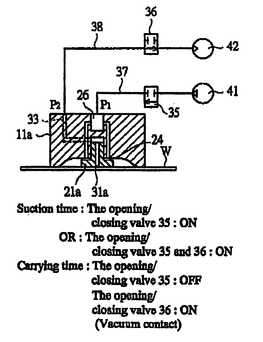
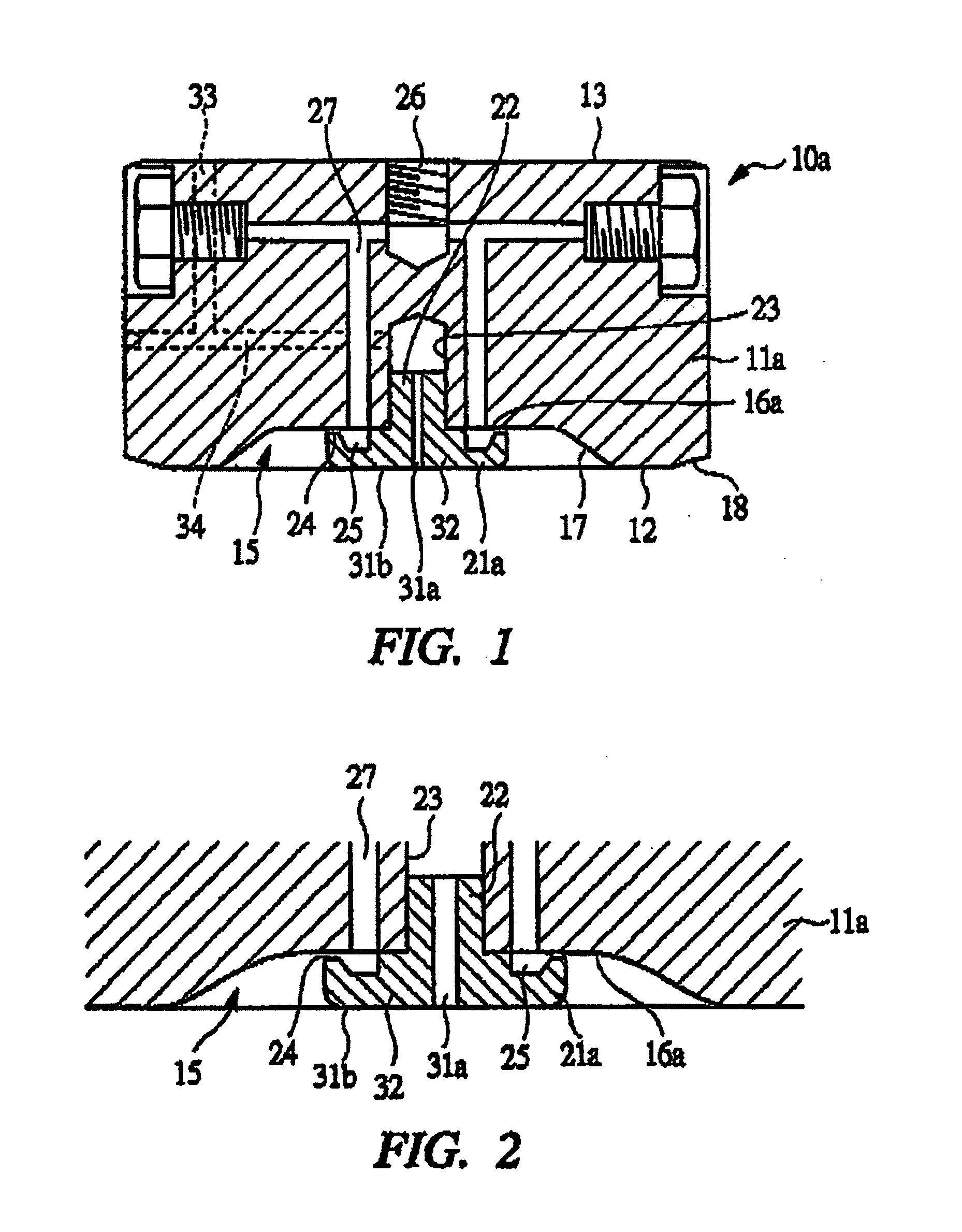
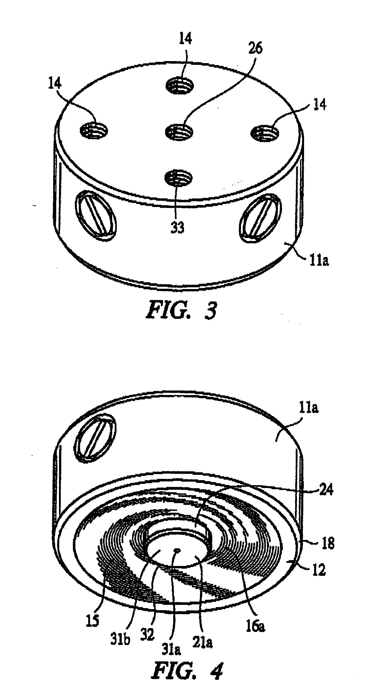
[0031] A carrying unit 10a has a carrying head 11a composed of a member whose outer periphery is circular and a workpiece holding face 12 is provided on the front end face of the carrying head 11a while a mounting face 13 is provided on the rear end face. Bolts are to be screwed into bolt tightening holes 14 formed in the carrying head 11a such that they are open to the mounting face 13 as shown in FIG. 3 and the carrying head 11a is mounted on a moving member such as a robot arm with bolts and driven vertically or horizontally by means of the moving member.

[0032] A concave portion 15 is formed in the front end face of the carrying head 11a such that it is dented to the side of the rear end relative to the workpiece holding face 12 by cutting out. This concave portion 15 has a bottom face 16a and an air guide face 17 which is continuous mildly from the bottom face 16a to the workpiece holding face 12. The air guide face 17 is of stream line type, comprised of a portion substantiall...


PUM


Abstract

This invention provides a carrying unit capable of changing the holding force of a carried object, suppressing the deformation amount of a carried object held by suction and dropping the carried object quickly at a predetermined place. A carrying unit has a workpiece holding face opposing a carried object and a carrying head equipped with a concave portion having an air guide face gently continued from a bottom face to a work holding face. A cylindrical nozzle which forms a slit for discharging air between the carrying head and the bottom face in order to discharge positive pressure air toward the air guide face from that slit is mounted on the carrying head such that it projects from the bottom face. A central portion of the cylindrical nozzle serves as a vertical nozzle comprised of a vertical hole which is open substantially in a vertical direction with respect to the carried object for supplying positive pressure or negative pressure air to the carried object and a flat portion perpendicular to the vertical hole.

Description

CROSS-REFERENCED TO RELATED APPLICATIONS [0001] Applicant hereby claims foreign priority benefits under U.S.C. §119 from Japanese Patent Application No. 2004-380657 filed on Dec. 28, 2004, the contents of which are incorporated by reference herein. BACKGROUND OF THE INVENTION [0002] The present invention relates to a carrying unit for carrying, for example, a sheet-like workpiece while holding it as a carried object. [0003] The carrying unit for carrying a workpiece such as a semiconductor wafer while holding it as a carried object from a workpiece supporting position to a processing position includes a type which carries the carried object by sucking it by vacuum and a type which carries the carried object while holding it in a non-contact condition without keeping the carried object in contact with a carrying head. [0004] As the former type, vacuum suction type is available and as the latter type, a non-contact carrying unit is available, which as described in Patent document 1(Ja...

Claims


Application Information

Patent Timeline
Patent Type & Authority Applications(United States)
IPC IPC(8): B25J15/06
CPCB65G47/91B24B37/042B25J9/042B65G49/07H01L21/68
Inventor TANAE, TOSHIKAZUKANEKO, YUKIO
Owner KOGANEI
Why Eureka
Try Eureka