PLL-based frequency synthesizer

a frequency synthesizer and phaselocked loop technology, applied in the direction of impedence networks, electrical equipment, automatic control, etc., can solve the problems of limiting the usable bandwidth of fractional pll and unsatisfactory fractional pll, and achieve the effect of increasing the speed of convergence of a frequency synthesizer

Inactive Publication Date: 2006-06-29
STMICROELECTRONICS SRL
View PDF5 Cites 21 Cited by
  • Summary
  • Abstract
  • Description
  • Claims
  • Application Information

AI Technical Summary

Benefits of technology

[0014] One object of the present invention is therefore increase the speed of convergence of a frequency synthesizer when the set point is modified, without using a fractional PLL.
[0018] As will be explained in the detailed description, the non-integer order of the loop filter of the PLL of the synthesizer according to the invention is used to obtain an attenuation for high frequencies that is between −20 dB / dec and −40 dB / dec. Thus, the bandwidth of the loop filter can be increased without incurring PLL instability.
[0021] In an embodiment, the low-pass cells are series RC cells. This embodiment is particularly advantageous when the first stage of the loop filter is a truncated first order RC filter (in other words having two poles). In practice, the alignment of the frequency response of the two stages of the loop filter is facilitated.

Problems solved by technology

This frequency is, however, obtained only as an average, over N periods of the reference signal, which has the direct consequence of producing spurious at the output.
These spurious limit the usable bandwidth of the fractional PLL.
For this reason, the fractional PLL is not entirely satisfactory from the point of view of the problem raised.

Method used


Image

  • PLL-based frequency synthesizer
  • PLL-based frequency synthesizer
  • PLL-based frequency synthesizer

Examples


Embodiment Construction

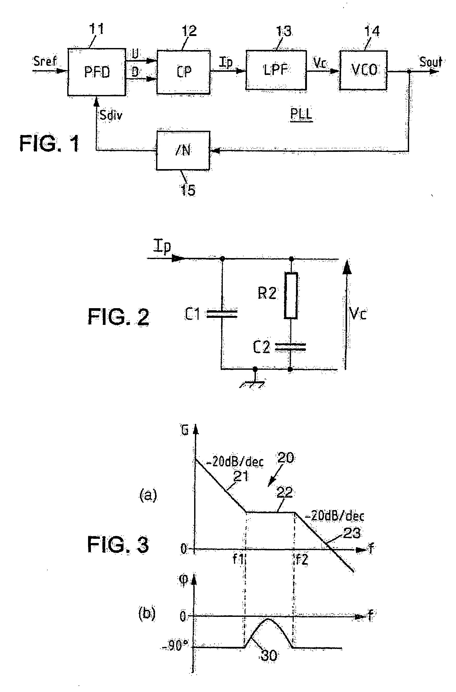
[0033] With reference to FIG. 1, a PLL used in a frequency synthesizer according to the prior art comprises a VCO 14 delivering a radiofrequency signal Sout, the frequency Fout of which is, for example, of the order of a few hundred MHz. This signal is addressed to a frequency divider 15 applying a variable division ratio N. By modifying the set point associated with N, the frequency of the output signal Sout is changed.

[0034] In the example considered, the PLL is a charge pump PLL (CP-PLL), which is one of the most widely used PLL structures. The divided-frequency signal Sdiv obtained from the frequency divider 15 is addressed to an input of a phase / frequency detector (PFD) 11 which also receives a reference signal Sref produced from a crystal oscillator. The frequency Fref of the signal Sref is, for example, approximately 10 MHz. To obtain a predefined frequency Fvco at the VCO 14 output, N=Fout / Fref is applied.

[0035] The PFD 11 has an output signal made up of two binary compone...


PUM


Abstract

The frequency synthesizer includes a phase-locked loop (PLL). The PLL includes an oscillator controlled to deliver an output signal at a predefined output frequency, a variable frequency divider to convert the output signal into a divided-frequency signal, a phase comparator to produce a signal measuring a phase difference between the divided-frequency signal and a reference signal at a reference frequency, and a loop filter to control the oscillator on the basis of the measurement signal. To increase the speed of convergence of the synthesizer if the set point is changed, the loop filter of the PLL is a fractional, i.e. non-integer, order low-pass filter.

Description

FIELD OF THE INVENTION [0001] The present invention relates to phase-locked loop (PLL)-based frequency synthesizers, and in particular, to radio frequency (RF) transmitters and / or receivers including PLL-based frequency synthesizers. BACKGROUND OF THE INVENTION [0002] A PLL conventionally comprises a voltage-controlled oscillator (VCO) producing a high frequency signal, a frequency divider (also called loop divider) converting the high frequency signal into a divided-frequency signal, a phase comparator producing a signal measuring a phase difference between the divided-frequency signal and a signal at a reference frequency, and a low-pass filter (also called loop filter) to which the measurement signal is applied and the output of which controls the VCO. [0003] In its application to frequency synthesis, the value of the division factor applied by the frequency divider is adapted to obtain a set point value of the VCO output signal frequency. In practice, the following equation appl...

Claims


Application Information

Patent Timeline
Patent Type & Authority Applications(United States)
IPC IPC(8): H03L7/00
CPCH03H7/06H03L7/0891H03L7/093H03L7/18
Inventor OUSTALOUP, ALAINDEVAL, YANNBELOT, DIDIERMELCHIOR, PIERREBEGUERET, JEAN-BAPTISTEBADETS, FRANCKLAGARESTE, VINCENT
Owner STMICROELECTRONICS SRL
Why Eureka
Try Eureka