Signal output apparatus, sheet identification apparatus, image forming apparatus including the same, and method for identifying sheet material

a signal output apparatus and output signal technology, applied in the direction of digitally marking record carriers, instruments, transportation and packaging, etc., can solve the problems of inability of signal output apparatus to apply stable impact strokes to sheet materials, and inability to respond to changes in impact and/or output signals

Inactive Publication Date: 2006-06-29
CANON KK
View PDF5 Cites 51 Cited by
  • Summary
  • Abstract
  • Description
  • Claims
  • Application Information

AI Technical Summary

Benefits of technology

[0038] According to at least one exemplary embodiment, the impact application member is capable of freely calibrating the impact by changing the velocity of the impact application member when an impact is being applied.
[0039] According to at least one exemplary embodiment, the impact application member is capable of freely calibrating the impact by changing the weight of the impact application member when an impact is being applied.

Problems solved by technology

However, the signal output apparatus discussed in Japanese Patent Laid-Open No. 2004-026486 is not capable of responding to changes in the impact and / or the output signal due to aging or degradation of the impact generating member.
In some cases, the signal output apparatus is not capable of applying stable impact strokes to the sheet material.
Moreover, changes in temperature and / or humidity may change the impact and / or the output signal due to thermal expansion of the members.
Moreover, if an impact application member that is easily affected by environmental changes is used, the impact and / or the output signal may change over time.
However, if the sheet material is not marked, the sheet material cannot be identified.
In other words, such a sheet identification apparatus is only capable of identifying a sheet material having a mark M and is not capable of identifying a sheet material without a mark M.
Furthermore, a special device for marking the sheet material and time for applying a mark are required, causing an increase in costs.
As a result, high-speed image formation becomes difficult.
As a result, the capability of the apparatus to identify a sheet material is reduced.

Method used


Image

  • Signal output apparatus, sheet identification apparatus, image forming apparatus including the same, and method for identifying sheet material
  • Signal output apparatus, sheet identification apparatus, image forming apparatus including the same, and method for identifying sheet material
  • Signal output apparatus, sheet identification apparatus, image forming apparatus including the same, and method for identifying sheet material

Examples


first exemplary embodiment

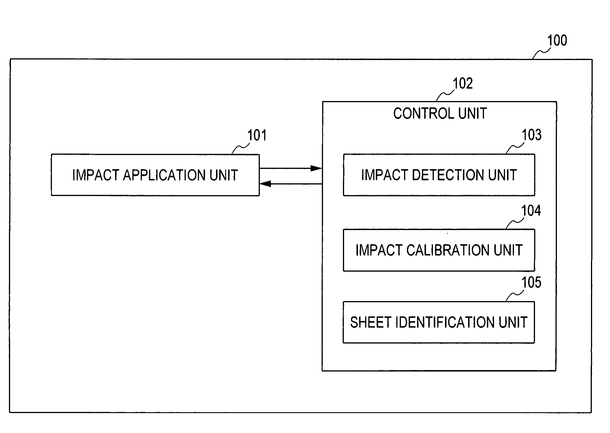
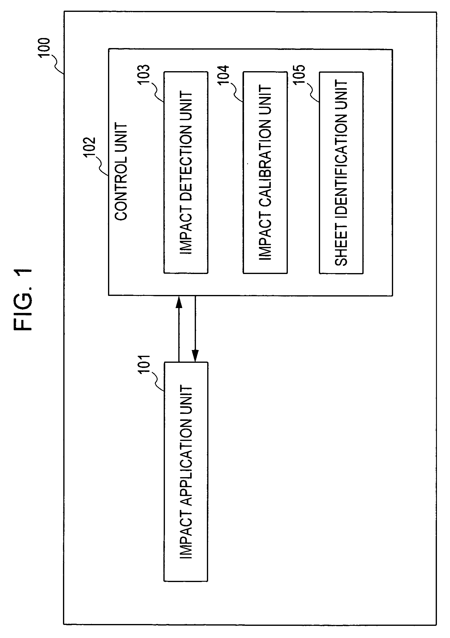
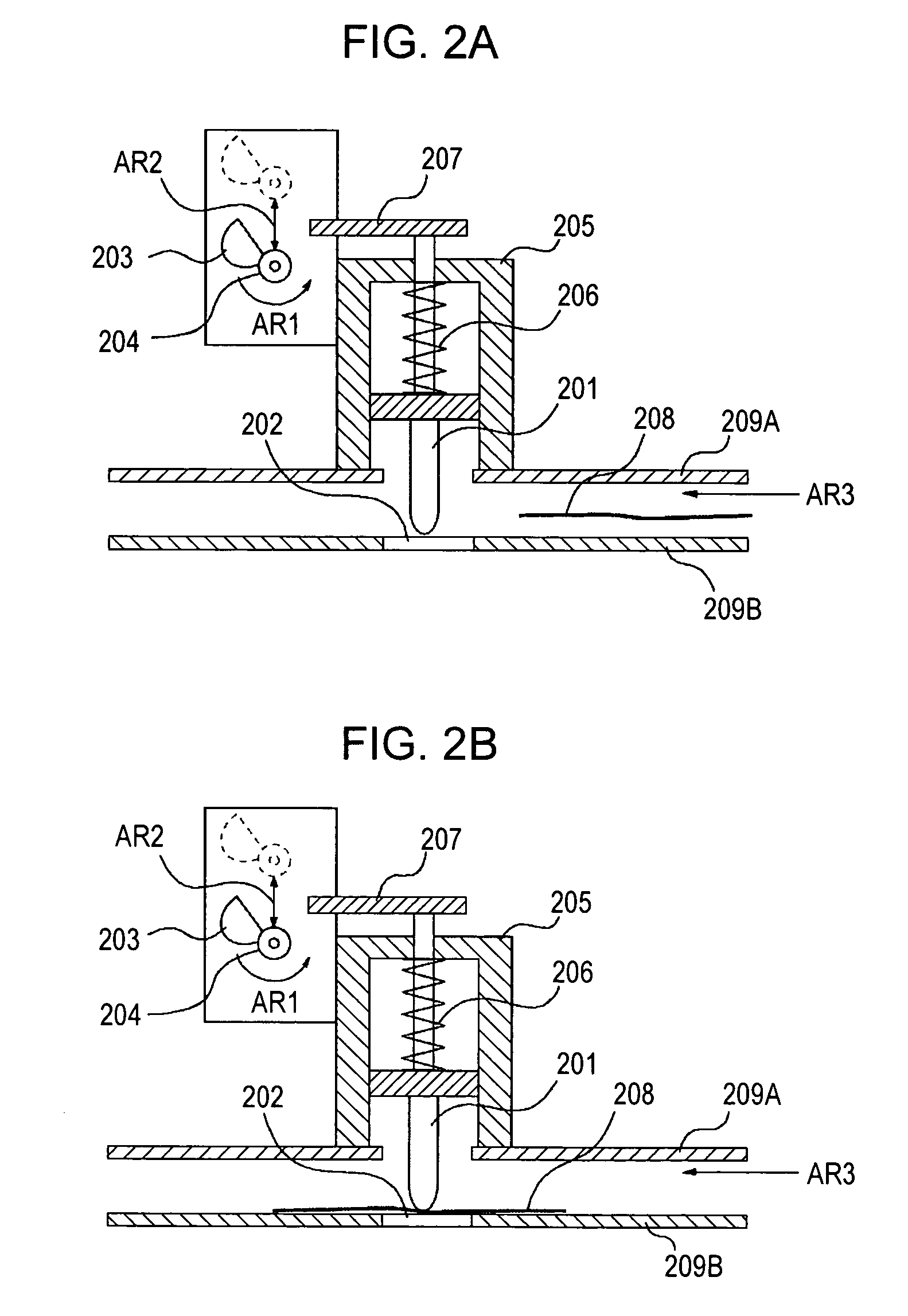
[0075] A sheet identification apparatus according to a first exemplary embodiment will be described with reference to FIGS. 1 to 3. FIG. 1 is a block diagram illustrating the functional structure of the sheet identification apparatus 100 according to the first exemplary embodiment. FIG. 2A is a cross-sectional view of a configuration adapted to detect the impact generated by an impact application member when a sheet material is not provided. FIG. 2B is a cross-sectional view of a configuration adapted to detect the impact generated by an impact application member when a sheet material is provided. FIG. 3 is flow chart illustrating an operational process for identifying a sheet material.

[0076] First, the functional structure of the sheet identification apparatus 100 according to the first exemplary embodiment will be described. The sheet identification apparatus 100 includes an impact application unit 101 and a control unit 102. The control unit 102 includes an impact detection unit...

second exemplary embodiment

[0104] A sheet identification apparatus according to a second exemplary embodiment will be described with reference to FIG. 4. FIG. 4 is a perspective view illustrating the structure of an impact application unit according to the second exemplary embodiment.

[0105] The sheet identification apparatus according to the second exemplary embodiment is similar to that according to the first exemplary embodiment except that the pulling mechanism realized by an impact application member 201 is modified. Reference numerals in FIG. 4 that are the same as those in FIGS. 2A and 2B represent the components that have the same structure as those in FIGS. 2A and 2B and descriptions thereof are omitted.

[0106] As shown in FIG. 4, a solenoid 401 is disposed above the impact application member 201 and is held by the guide 205 so that the movement direction of the impact application member 201 is set. A solenoid terminal block 402 is a terminal configured to supply an electric current setting the attra...

third exemplary embodiment

[0121] Next, a sheet identification apparatus according to a third exemplary embodiment will be described with reference to FIG. 5. FIG. 5 is a cross-sectional view illustrating the structure of an impact application unit according to the third exemplary embodiment. Reference numerals in FIG. 5 that are the same as those in FIGS. 2A and 2B represent the components that have the same structure as those in FIGS. 2A and 2B and descriptions thereof are omitted. However, in this exemplary embodiment, the fixed shaft 204 only moves in the direction indicated by the arrow AR1.

[0122] As shown in FIG. 5, the solenoid 501 is disposed above the impact increasing member 207. The terminal block 502 is a terminal configured to supply an electric current that determines the suction force of the solenoid 401. An ‘n’ (n>1) number of weights 503 are provided. The weights 503 are magnetized by the solenoid 501 and are either attracted to the solenoid 501 or disposed above the impact increasing member...


PUM


Abstract

At least one exemplary embodiment is directed to a signal output apparatus including an impact application unit configured to generate and apply an impact to a sheet material, an impact reception unit configured to receive the applied impact, a signal output unit configured to output a signal in response to the impact received by the impact reception unit from the impact application unit and a calibration unit configured to calibrate at least one of the impact applied by the impact application unit and the signal output from the signal output unit.

Description

BACKGROUND OF THE INVENTION [0001] 1. Field of the Invention [0002] The present invention relates to a signal output apparatus, and more particularly, though not exclusively, to an identification apparatus configured to identify characteristics of a sheet material. [0003] 2. Description of the Related Art [0004] A conventional image forming apparatus, (e.g., a copy machine, a printer, or a facsimile machine), forms images on a recording medium (e.g., sheet material). The sheet material used for image formation may be regular paper, such as copy paper, glossy paper, coated paper, recycled paper, overhead projector (OHP) film, or other sheet material capable of having an image formed thereon as known by one of ordinary skill in the relevant arts and equivalents. [0005] For an image forming apparatus to form high quality images on various different sheet materials, it is desirable for the image forming apparatus to be able to carry out image formation in accordance with the type of the...

Claims


Application Information

Patent Timeline
Patent Type & Authority Applications(United States)
IPC IPC(8): G06F15/00H04N1/60G06K1/00
CPCB65H7/02B65H2511/416B65H2513/30B65H2515/34B65H2515/84B65H2551/20B65H2553/61B65H2553/614B65H2557/61B65H2557/64B65H2801/06B65H2220/03B65H2220/01B65H2220/02
Inventor MORIMOTO, TOSHITSUGUKANASHIKI, MASAAKIKANEKO, NORIOKAWASAKI, TAKEHIKO
Owner CANON KK
Why Eureka
Try Eureka