Iris imaging using reflection from the eye

a technology of iris and reflection, applied in the field of human iris imaging, can solve the problems of 15 cm wide field of view, inacceptable spatial resolution, and significant worsening of standoffs, and achieve the effect of prolonging the usable exposure tim

Active Publication Date: 2006-06-29
TASCENT INC
View PDF12 Cites 99 Cited by
  • Summary
  • Abstract
  • Description
  • Claims
  • Application Information

AI Technical Summary

Benefits of technology

[0010] The present invention overcomes the limitations of the prior art by providing a rapid iris imaging system that can be used at longer standoff distances and over larger capture volumes, without the active cooperation of subjects. Light illuminates the subjects' eyes. Reflection from the eyes (e.g., retro-reflection from the retina or glint reflection from the...

Problems solved by technology

The situation becomes significantly worse at longer standoffs.
For example, if the same camera were used at a standoff of 10 m, maintaining the same angular resolution would result in a spatial resolution of 750 μm per pixel, which is unacceptable.
On the other hand, maintaining a spatial resolution of 75 μm per pixel would result in a 15 cm wide field of view at 10 m. Keeping the iris within this field of view is also very difficult.
The CCD-based system described above and other similar traditional systems have a small capture vol...

Method used


Image

  • Iris imaging using reflection from the eye
  • Iris imaging using reflection from the eye
  • Iris imaging using reflection from the eye

Examples


Embodiment Construction

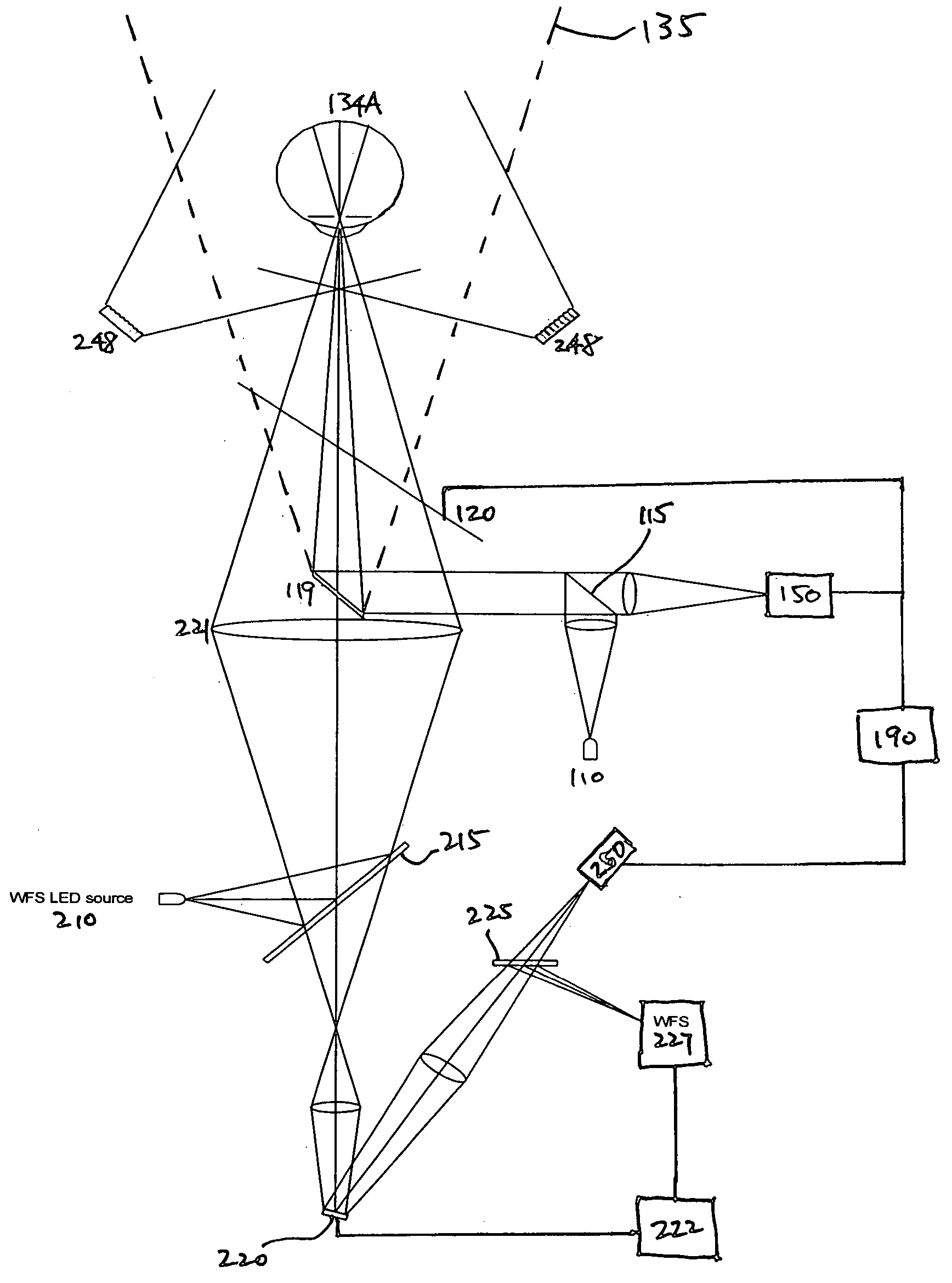
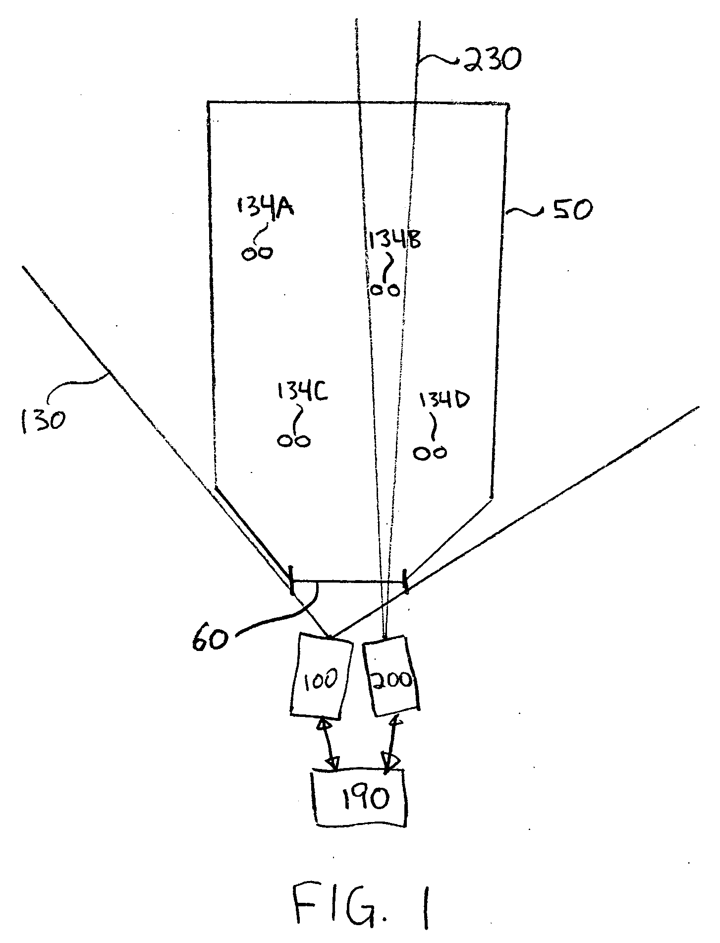
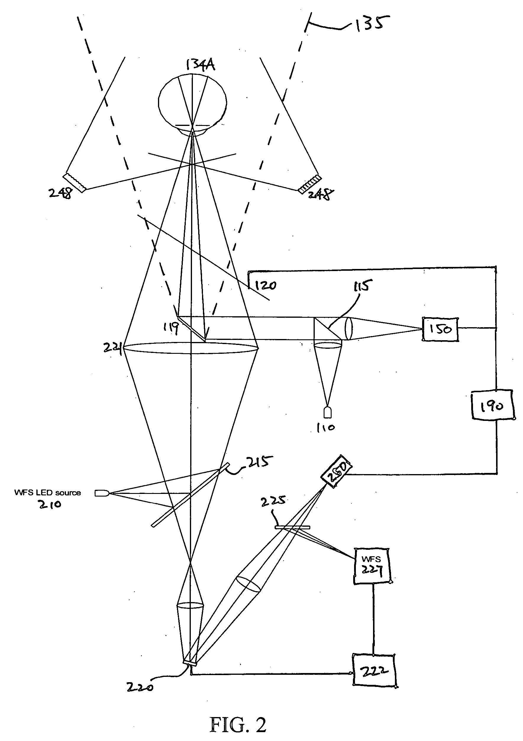
[0022]FIG. 1 is an illustration of an iris imaging system according to the present invention. The iris imaging system includes an imaging subsystem 200 and, optionally, an acquisition subsystem 100. The system is designed to capture iris images of many eyes 134 over a large capture volume 50, typically without the active cooperation of the subjects. In one application, the subjects are passing through a portal 60 (such as a doorway or metal detector), the capture volume 50 is the entranceway leading up to the portal, and the iris imaging system captures iris images as the subjects pass through the capture volume. In many applications, the capture volume can be defined based on a portal or other bottleneck for the flow of people. Examples include corridors, turnstyles, toll booths, elevator doors, escalators and parking garage entrances. Other examples include checkout lines or other queues, crosswalks, sidewalks and roadways.

[0023] This situation typically is “uncooperative,” meani...


PUM


Abstract

A rapid iris acquisition, tracking, and imaging system can be used at longer standoff distances and over larger capture volumes, without the active cooperation of subjects. The captured iris images can be used for biometric identification. Light illuminates the subjects' eyes. Eye reflection from the eyes is used to steer a high resolution camera to the eyes in order to capture images of the irises.

Description

CROSS-REFERENCE TO RELATED APPLICATION(S) [0001] This application claims priority under 35 U.S.C. § 119(e) to U.S. Provisional Patent Application Ser. No. 60 / 654,638, “Biometric Identification and Iris Imaging Using Retinal Retro-Reflection,” filed Feb. 17, 2005; and to U.S. Provisional Patent Application Ser. No. 60 / 634,331, “Adaptive Optics (AO) Imaging Applied to Biometric Identification Using Iris Imaging,” filed Dec. 7, 2004. The subject matter of all of the foregoing is incorporated herein by reference in their entirety.BACKGROUND OF THE INVENTION [0002] 1. Field of the Invention [0003] This invention relates to imaging of the human iris, as may be used for biometric identification. [0004] 2. Description of the Related Art [0005] As traditional forms of personal identification become vulnerable to advancing technology, biometric identification is increasingly seen as a viable approach to personal identification. Techniques such as voice recognition, fingerprinting, and iris im...

Claims


Application Information

Patent Timeline
IPC IPC(8): G06K9/00A61B3/10
CPCA61B3/1216A61B5/117G06K9/00604A61B5/1171G06V40/19A61B3/10G06F18/00
Inventor NORTHCOTT, MALCOLM J.GRAVES, J. ELON
Owner TASCENT INC
Why Eureka
Try Eureka