Thrust slide bearing

Active Publication Date: 2006-06-29
OILES CORP
View PDF0 Cites 19 Cited by
  • Summary
  • Abstract
  • Description
  • Claims
  • Application Information

AI Technical Summary

Benefits of technology

[0006] The present invention has been devised in view of the above-described aspects, and its object is to provide a thrust sliding bearing which makes it possible to allow a lubricant such as grease to be present on the sliding surface over long periods of time and use such a lubricant for receiving the thrust load, in which even if the thrust load increases, the friction torque practically does not change to make it possible to

Problems solved by technology

However, the rolling bearing has a possibility that fatigue failure occurs in the balls or needles due to fine vibrations and vibration load or the like, and there is a problem in that it is difficult to maintain smooth steering operation.
The sliding bearing has problems in that since its friction torque is high as compared with the rolling bearing, an increase in the thrust load results in an inc

Method used


Image

  • Thrust slide bearing
  • Thrust slide bearing
  • Thrust slide bearing

Examples


Example

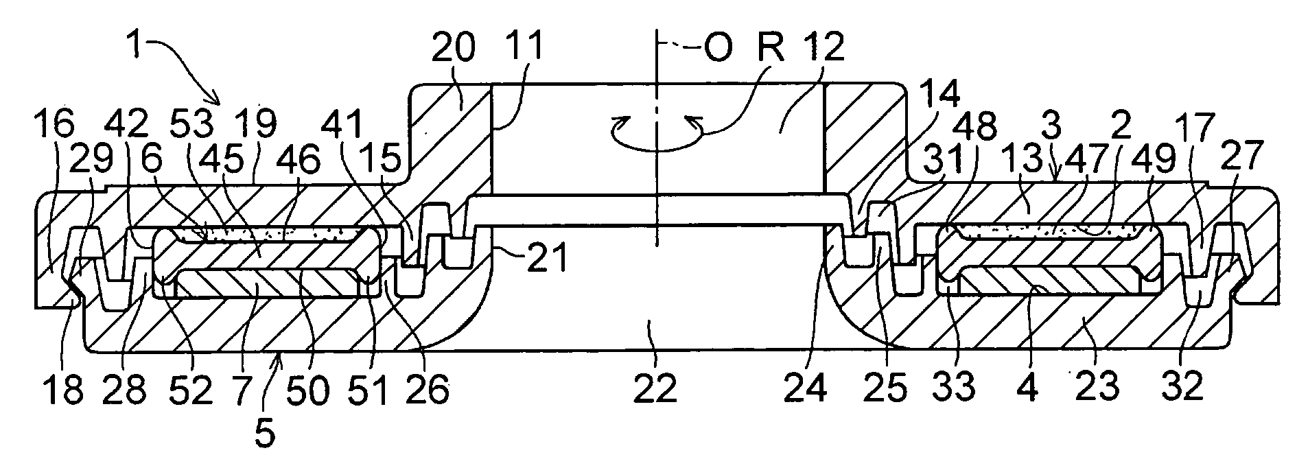
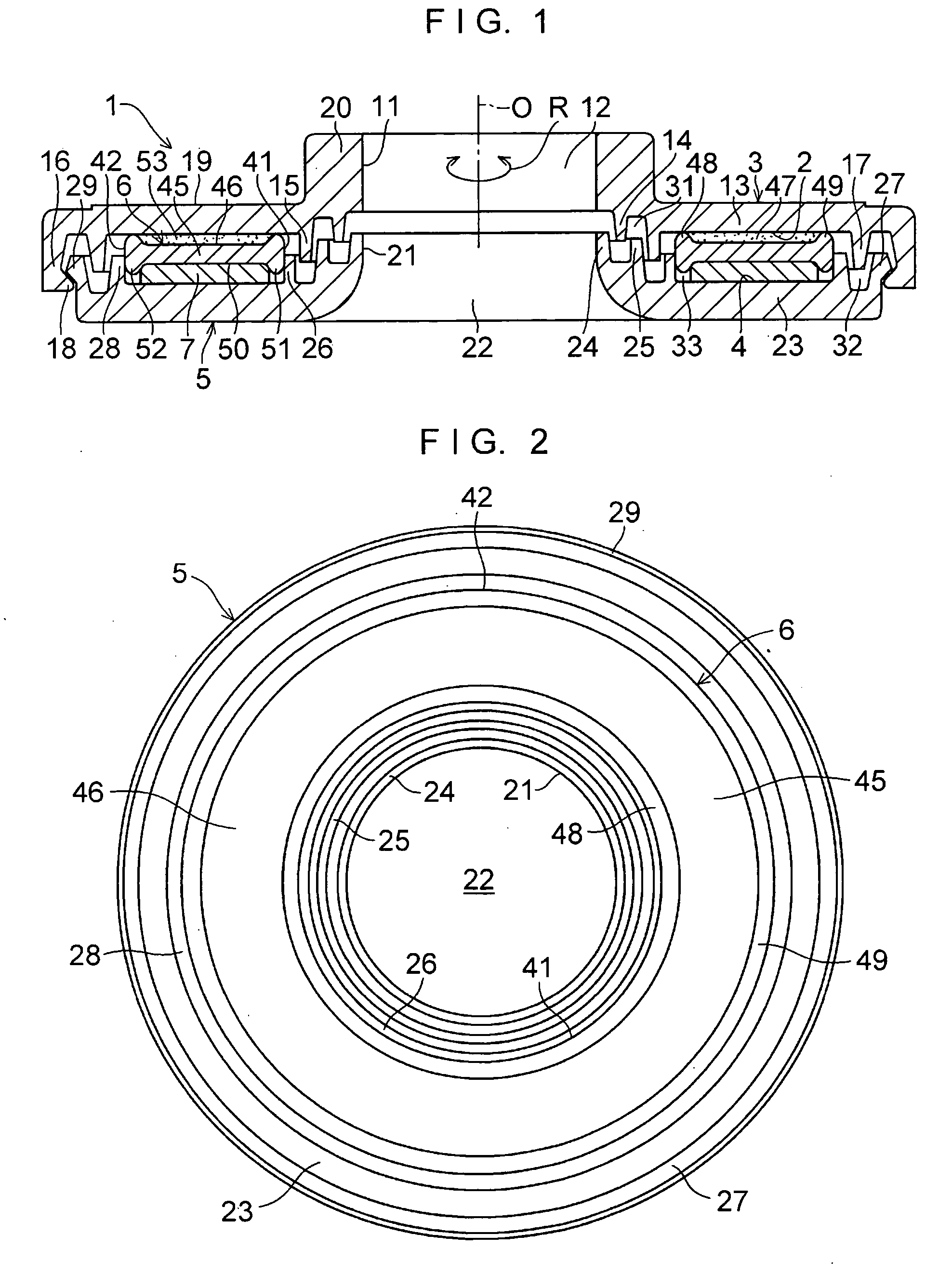
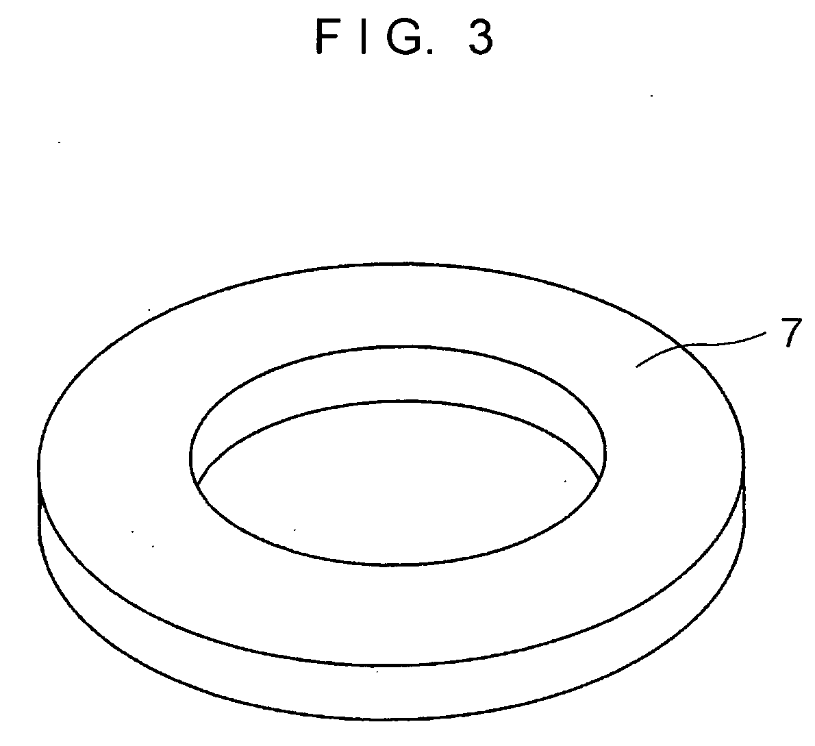
[0024] In FIGS. 1 to 3, a thrust sliding bearing 1 for use in a strut-type suspension in a four-wheeled vehicle in accordance with this embodiment is comprised of an upper casing 3 which is made of a synthetic resin such as polyacetal resin, has an annular surface 2, and serves as a first bearing body; an annular lower casing 5 which is made of a synthetic resin such as polyacetal resin, is superposed on the upper casing 3 so as to be rotatable about an axis 0 of the upper casing 3 in an R direction, has an annular surface 4 opposed to the annular surface 2 of the upper casing 3, and serves as a second bearing body; and a thrust sliding bearing piece 6 and an elastic ring 7 which are superposed on top of each other and are interposed between the annular surfaces 2 and 4.

[0025] The annular upper casing 3 having a through hole 12 defined by an inner peripheral surface 11 includes an annular upper casing body portion 13 having the annular surface 2; an innermost peripheral-side cylind...


PUM


Abstract

A thrust sliding bearing (1) includes an upper casing (3) having an annular surface (2); an annular lower casing (5) which is superposed on the upper casing (3) so as to be rotatable about an axis (O) of the upper casing (3) and has an annular surface (4) opposed to the annular surface (2) of the upper casing (3); and an annular thrust sliding bearing piece (6) and an elastic ring (7) which are superposed on top of each other and are interposed between the annular surfaces (2) and (4).

Description

TECHNICAL FIELD [0001] The present invention relates to a thrust sliding bearing, and more particularly to a thrust sliding bearing which is suitably incorporated as a thrust sliding bearing of a strut-type suspension (Macpherson type) in a four-wheeled vehicle. BACKGROUND ART [0002] In general, a strut-type suspension is mainly used in a front wheel of a four-wheeled vehicle, and is constructed such that a strut assembly incorporating a hydraulic shock absorber in a cylinder formed integrally with a main shaft is combined with a coil spring. Among such suspensions, there is a type of structure in which the axis of the coil spring is actively offset with respect to the axis of the strut, so as to allow the sliding of a piston rod of the shock absorber incorporated in the strut to be effected smoothly. There is another type of structure in which the coil spring is disposed by aligning the axis of the coil spring with the axis of the strut. In either structure, a thrust bearing is dis...

Claims


Application Information

Patent Timeline
IPC IPC(8): F16C17/04B60G15/06F16C27/06F16C27/08F16C33/10F16C33/20
CPCB60G15/068B60G2204/128B60G2204/418F16C17/04F16C2361/53F16C27/08F16C33/102F16C33/74F16C27/063F16C2326/05B60G15/06F16C33/20
Inventor MIYATA, KAZUYUKIKANEKO, RYOHEI
Owner OILES CORP
Why Eureka
Try Eureka