Image forming apparatus

a technology of forming apparatus and forming chamber, which is applied in the direction of electrographic process apparatus, instruments, optics, etc., can solve the problems of increasing and decreasing the glossiness of wax

Active Publication Date: 2006-06-29
KONICA MINOLTA BUSINESS TECH INC
View PDF2 Cites 14 Cited by
  • Summary
  • Abstract
  • Description
  • Claims
  • Application Information

AI Technical Summary

Benefits of technology

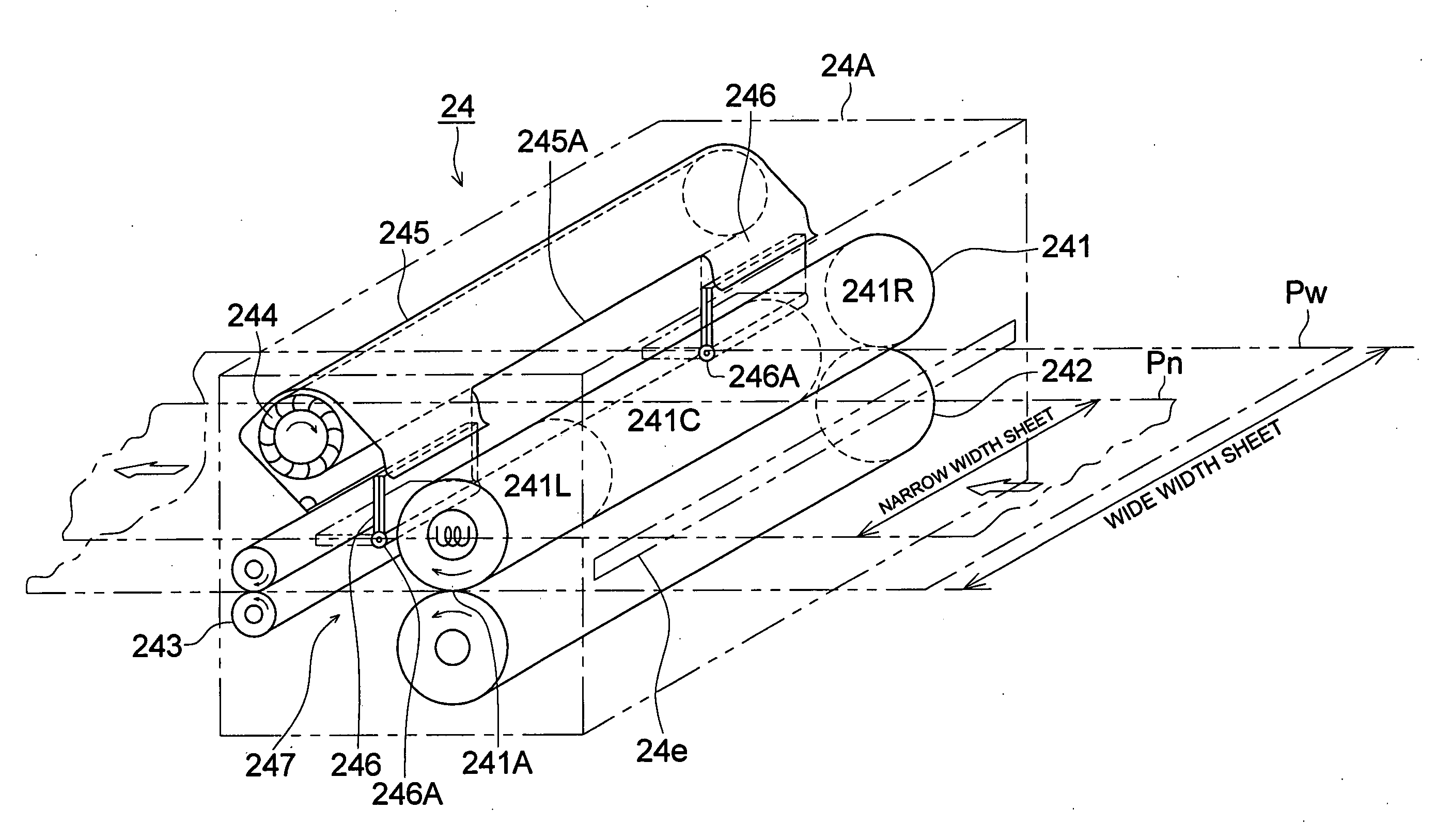
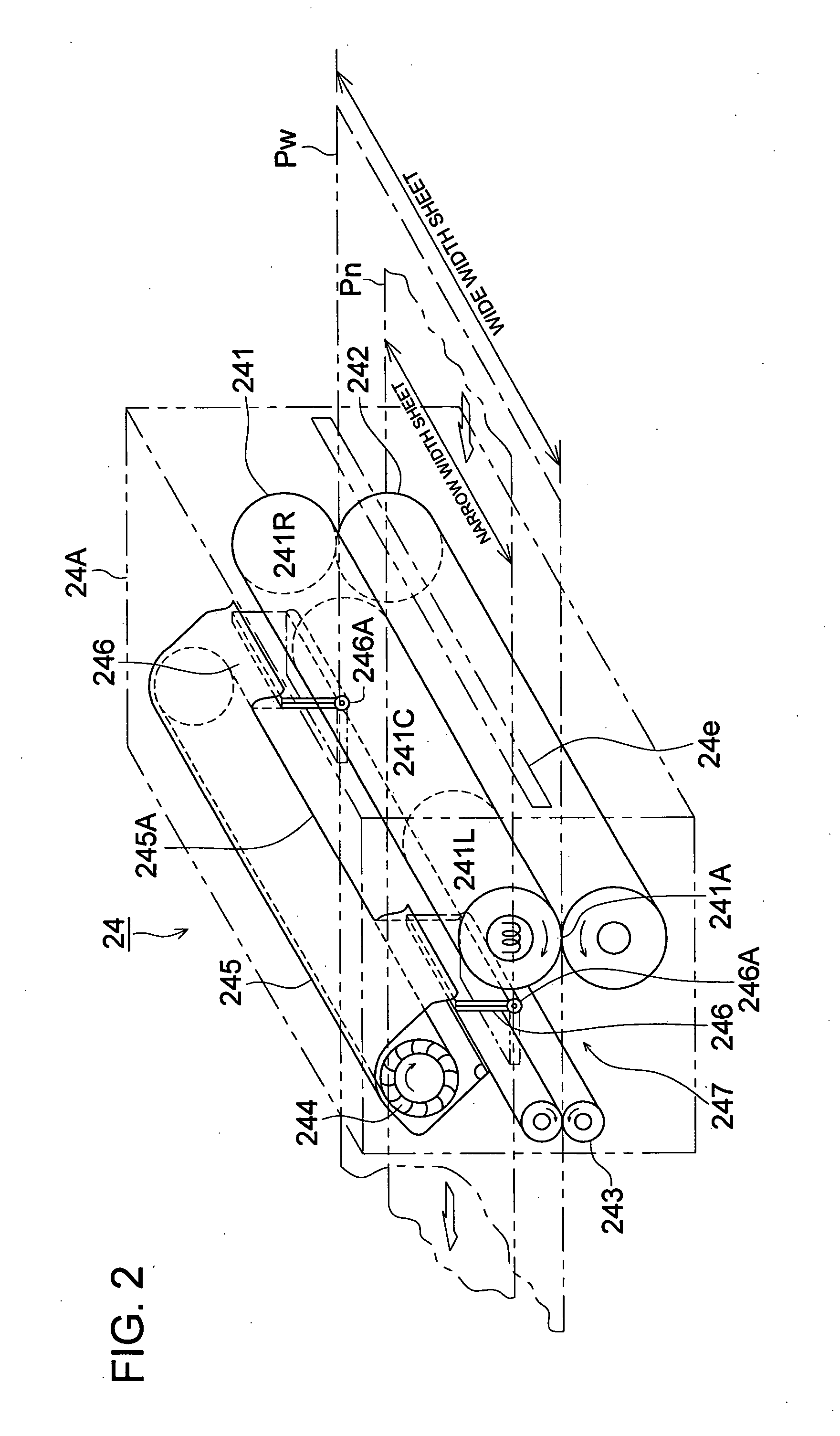
[0011] One of the objects of the present invention is to provide a small-space low-cost image forming apparatus with a simplified construction, when using a toner that includes wax, by solving the problems of conventional fixing unit of the above type, by carrying out appropriately and without wastage using a single air blower the air blowing for appropriate cooling of the fixing members such as the heat roller or the endless heating belt of the fixing unit, and the air blowing to the downstream side inside the fixing unit immediately after fixing by applying heat and pressure, so that, depending on the size of the image supporting material, the path of the air blow is changed appropriately and the fixing operation is carried out in a stable manner.

Problems solved by technology

Firstly, regarding the edge part temperature rise of heating sections such as the heat roller in a fixing unit, at the time of fixing sheets with small sizes, although there is the problem that the fixing temperature of parts through which the paper does not pass rises excessively, the technique of forced air cooling selectively the edge parts of the fixing apparatus is present as a conventional technology, as disclosed in Patent Document 1 and Patent Document 2.
Secondly, when using toners that include wax, regarding the conveyance rubbing marks occurring on the downstream side of the fixing unit, although wax oozes out on the surface of a fixed image of a toner that includes wax, there is the trend of the glossiness of the wax increasing if cooled suddenly near the crystallization temperature and of the glossiness of the wax decreasing if cooled slowly.
As a consequence, the image rubs against conveying rollers and guiding members on the downstream side of the fixing unit, and rubbing marks remain upon sudden cooling.
In addition, since conveying force cannot be generated, there will be limitations on the conveying path.
In view of this, air is blown and slow cooling (or fast cooling) is done immediately after fixing.
In this manner, in an image forming apparatus using toners that include wax, in order to solve the above problems, at least two systems of air blowing unit were required in a conventional fixing unit, and hence the apparatus became large in size and higher in cost.

Method used


Image

  • Image forming apparatus
  • Image forming apparatus
  • Image forming apparatus

Examples


Embodiment Construction

[0017] A preferred embodiment of the present invention is described below. Further, the descriptions given here shall not be construed to limit the technical scope of the claims or the meanings of the technical terms. In addition, in the following, the assertive explanations of the preferred embodiment of the present invention merely indicate the best mode and shall not be construed to limit the meanings of technical terms or the technical scope of the present invention.

[0018] Further, although the explanations given here assume a heat roller as the fixing member and a pressing roller as the pressing member of the fixing apparatus used in the present invention, it goes without saying that it is also possible to use an endless heated belt as the fixing member and to use any item other than a pressing roller as the pressing member.

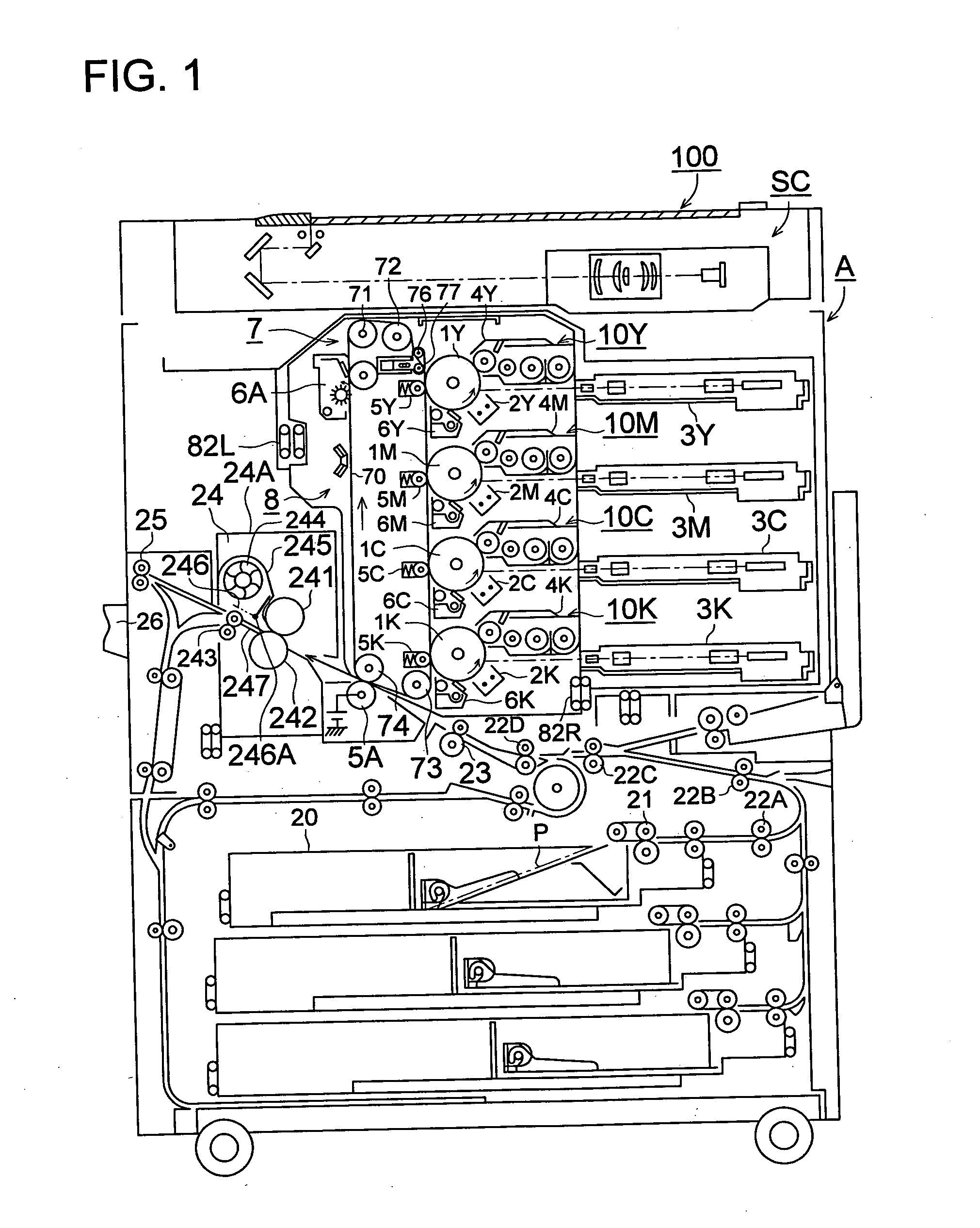
[0019]FIG. 1 is an outline configuration diagram showing a color image forming apparatus as a preferred embodiment of the present invention.

[0020] This i...


PUM


Abstract

An image forming apparatus provided with a fixing unit, the fixing unit comprising: a fixing member having a heating member therein; a pressing member that presses against the fixing member, wherein an image supporting material carrying a toner image is grasped and conveyed by a nipping portion formed between the fixing member and the pressing member and the toner image is fixed by applying heat and pressure at the nipping portion; an air blowing section provided downstream of the nipping portion on a conveying path of the image supporting material; and an air flow path switching section that switches an air blow of the air blowing section in accordance with a size of the image supporting material for both ends of the conveying path and for both ends of the fixing member.

Description

[0001] This application is based on Japanese Patent Application No. 2004-376308 filed on Dec. 27, 2004, which is incorporated hereinto by reference. BACKGROUND OF THE INVENTION [0002] The present invention relates to an image forming apparatus that eliminates problems such as rubbing marks caused by oozing of wax that occurs during the cooling of a fixing unit installed in an image forming apparatus using toners that include wax. [0003] A fixing unit installed in an image forming apparatus is provided with a mechanism that carries out fixing by heating while nipping and conveying the image supporting material which is the transfer material having the transferred image on it using, for example, a heat roller as the fixing member and using, for example, a pressure roller as the pressing member that presses against and is in contact with the heat roller. [0004] Further, related to such fixing units: [0005] Firstly, regarding the edge part temperature rise of heating sections such as th...

Claims


Application Information

Patent Timeline
Patent Type & Authority Applications(United States)
IPC IPC(8): G03G21/20
CPCG03G15/6573G03G15/2017
Inventor NAGASE, HISAYOSHI
Owner KONICA MINOLTA BUSINESS TECH INC
Why Eureka
Try Eureka