Gas turbine

a gas turbine and gas turbine technology, applied in the direction of machines/engines, liquid fuel engines, mechanical equipment, etc., can solve the problems of big obstruction, and achieve the effect of significantly shortening the shutdown period of the gas turbine for the replacement of sensors

Active Publication Date: 2006-06-29
MITSUBISHI HEAVY IND LTD
View PDF4 Cites 32 Cited by
  • Summary
  • Abstract
  • Description
  • Claims
  • Application Information

AI Technical Summary

Benefits of technology

[0033] In the gas turbine in accordance with the present invention, because the sensors detecting the clearances between the tips of the rotating blades and the inner circumference surfaces of the ring segments can surely be pulled out and inserted from the outside of the casing, being integrated together with the first guide pipe penetrating through the blade rings from the outside

Problems solved by technology

However, it was discovered that in the conventional construction of installation of a sensor as described above, the following issues would occur due to being subject to vibrations during operation of a gas turbine.
Therefore, especially the third issue is directly related to the shutdown period of a gas turbine, so that consequently it will become a bi

Method used


Image

  • Gas turbine
  • Gas turbine
  • Gas turbine

Examples


Embodiment Construction

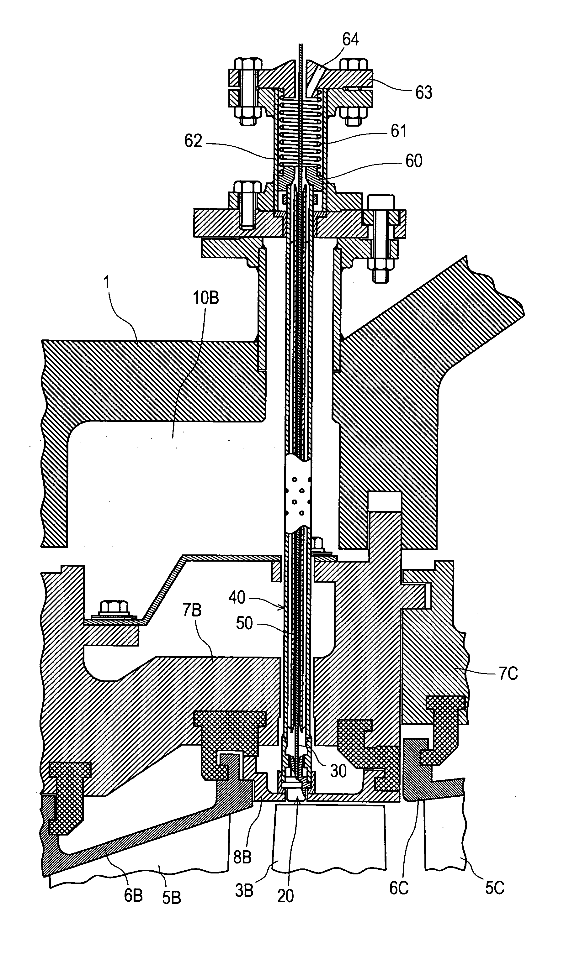
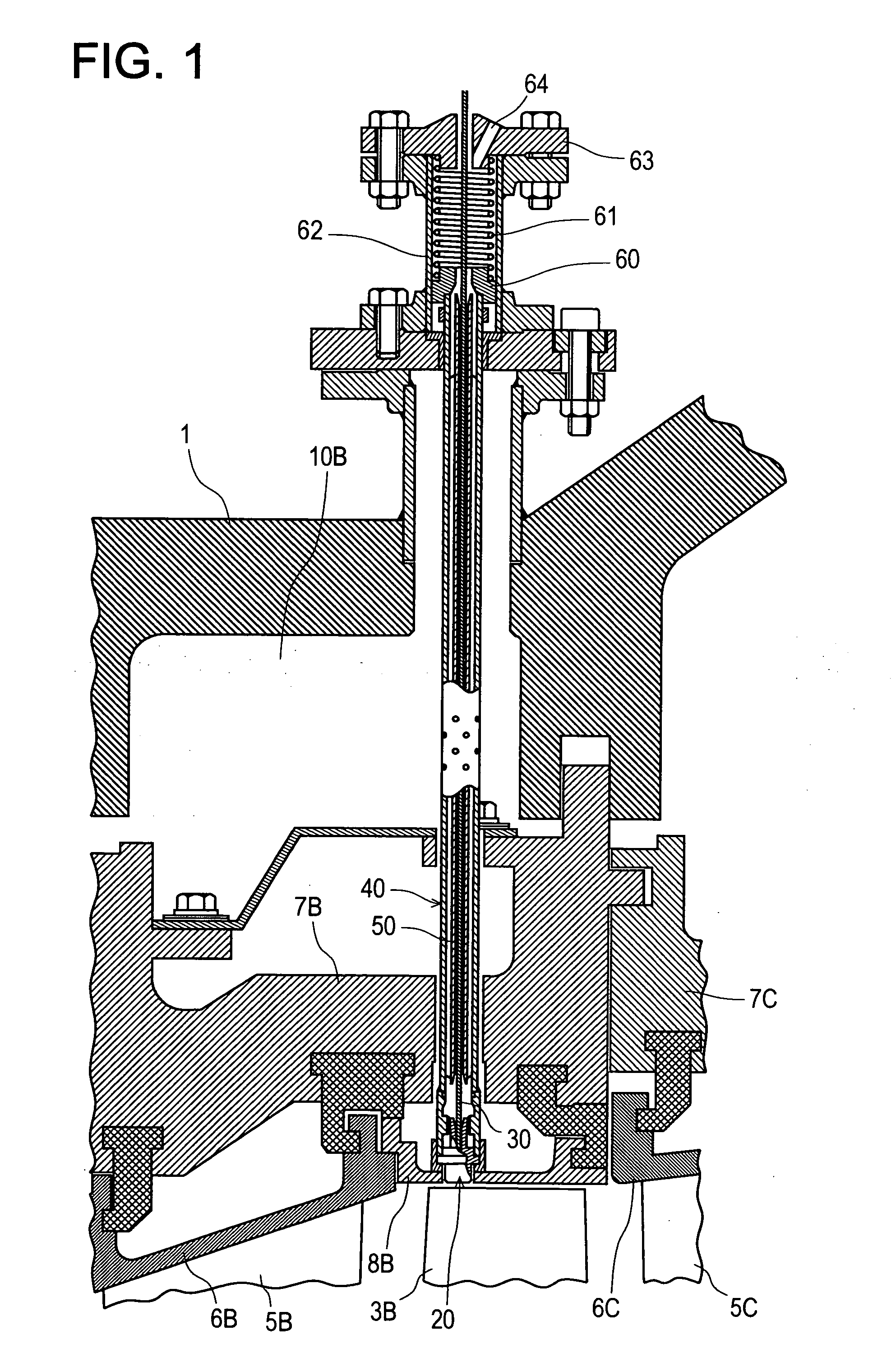
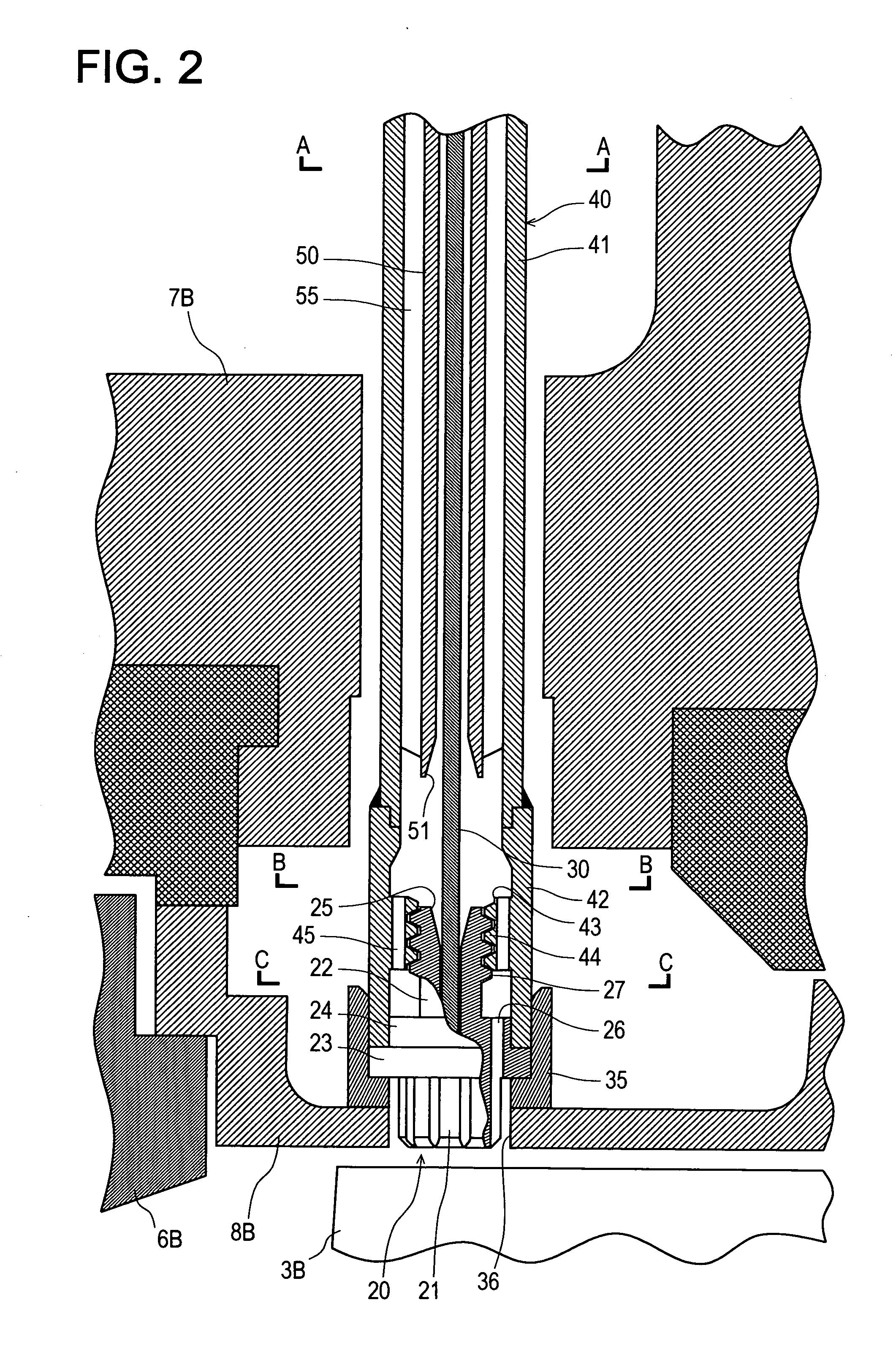
[0045] Referring now to the drawings, an embodiment of the present invention will be described hereinafter. FIG. 1 is a longitudinal cross-sectional view showing the entire construction of installation of a sensor in a gas turbine in accordance with an embodiment of the present invention; FIG. 2 is a longitudinal cross-sectional view being enlarged and showing the vicinity of a sensor that includes necessary portions of the construction of installation of the sensor; and FIG. 3 is a longitudinal cross-sectional view being enlarged and showing other necessary portions of the construction of installation of the sensor, from the casing to the vicinity of a blade ring. FIG. 4 is a cross-sectional view cut at A-A of FIG. 2; FIG. 5 is a cross-sectional view cut at B-B of FIG. 2; FIG. 6 is a cross-sectional view cut at C-C of FIG. 2; and FIG. 7 is a cross-sectional view cut at D-D of FIG. 3.

[0046] As shown in FIG. 1 and FIG. 2, a gas turbine in accordance with this embodiment of the prese...


PUM


Abstract

Such a gas turbine is provided as can put into practical use a control technology which detects clearance between the tip of rotating blade and the inner circumference surface of ring segment surrounding them and adjusts the temperature, the pressure and the flow volume of the cooling fluid for blade rings/ring segments and the cooling fluid for rotors based on the output. A sensor is provided to detect the clearance between the tip of the rotating blade and the inner circumference surface of the ring segment. A sensor is integrated together with a first guide pipe by having a posterior portion thereof screwed together to a secondary pipe being installed to an edge of the first guide pipe inside of which a cooling fluid is introduced into. The first guide pipe is pressed to the blade ring from the outside of the casing so as to retain. The sensor and the first guide pipe being integrated together by being screwed together will not be separated although they are subject to vibrations during operation of a gas turbine and can be pulled out and inserted from the outside of the casing in replacement.

Description

[0001] The present invention is based on the Japanese Patent Application No. 2004-375536 applied on Dec. 27, 2004. BACKGROUND OF THE INVENTION [0002] 1. Field of the Invention [0003] The present invention relates to a gas turbine, and especially, relates to a gas turbine which is expected to put such control technology into practical use as controls the temperature, pressure and flow volume of a cooling fluid for blade rings and segment rings in order to cool stationary vanes and rotating blades and of a cooling fluid for a rotor. [0004] 2. Description of the Prior Art [0005] Generally, a gas turbine mainly consists of three elements including an air compression part (“compressor” hereinafter), a combustion part (“combustor” hereinafter) and a turbine part; wherein a combustor is installed between the compressor and the turbine part that are directly connected to each other by a main shaft. Here, FIG. 8 shows a longitudinal cross-sectional view of a turbine part of a general gas tur...

Claims


Application Information

Patent Timeline
IPC IPC(8): F01D11/08
CPCF01D11/24F01D17/02Y02T50/676F05D2260/20Y02T50/60
Inventor TANIOKA, TADATERU
Owner MITSUBISHI HEAVY IND LTD
Why Eureka
Try Eureka