Massaging apparatus and forearm massager

Inactive Publication Date: 2006-06-29
FAMILY INADA
View PDF4 Cites 49 Cited by
  • Summary
  • Abstract
  • Description
  • Claims
  • Application Information

AI Technical Summary

Benefits of technology

[0012] The present invention has been made in view of the above. It is an objective of the present invention to provide a massaging apparatus and a forearm massager for use with the massaging apparatus. The massaging app

Problems solved by technology

However, the above massaging apparatus disclosed in Japanese Laid-Open Publication No. 2001-204776 has a problem as described below.
This caused a problem in which, even when the massaging apparatus is used as a mere comfort chair or when the massaging apparatus is not used for the purpose of massaging the forearm (e.g., when the massaging apparatus is used for massaging a body member other than the forearm), the user was required to insert the forearm to the arm holding portion.
The insertion of the forearm to the arm holding portion as described above caused limitation on the posture of the user, making it difficult for the user to take a desired posture due to the arm holding portion as an obstacle.
S52-28517 had a similar problem because it has a construction in which the leg portion or the arm portion of the user is retained by the fixation frame and the movable frame

Method used


Image

  • Massaging apparatus and forearm massager
  • Massaging apparatus and forearm massager
  • Massaging apparatus and forearm massager

Examples


embodiment 1

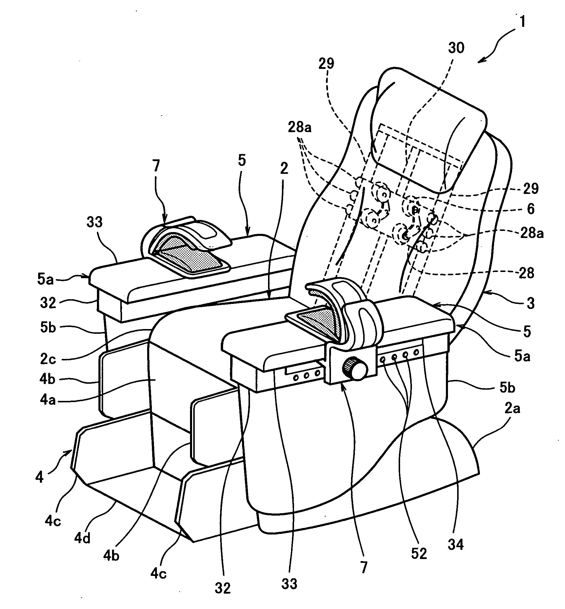
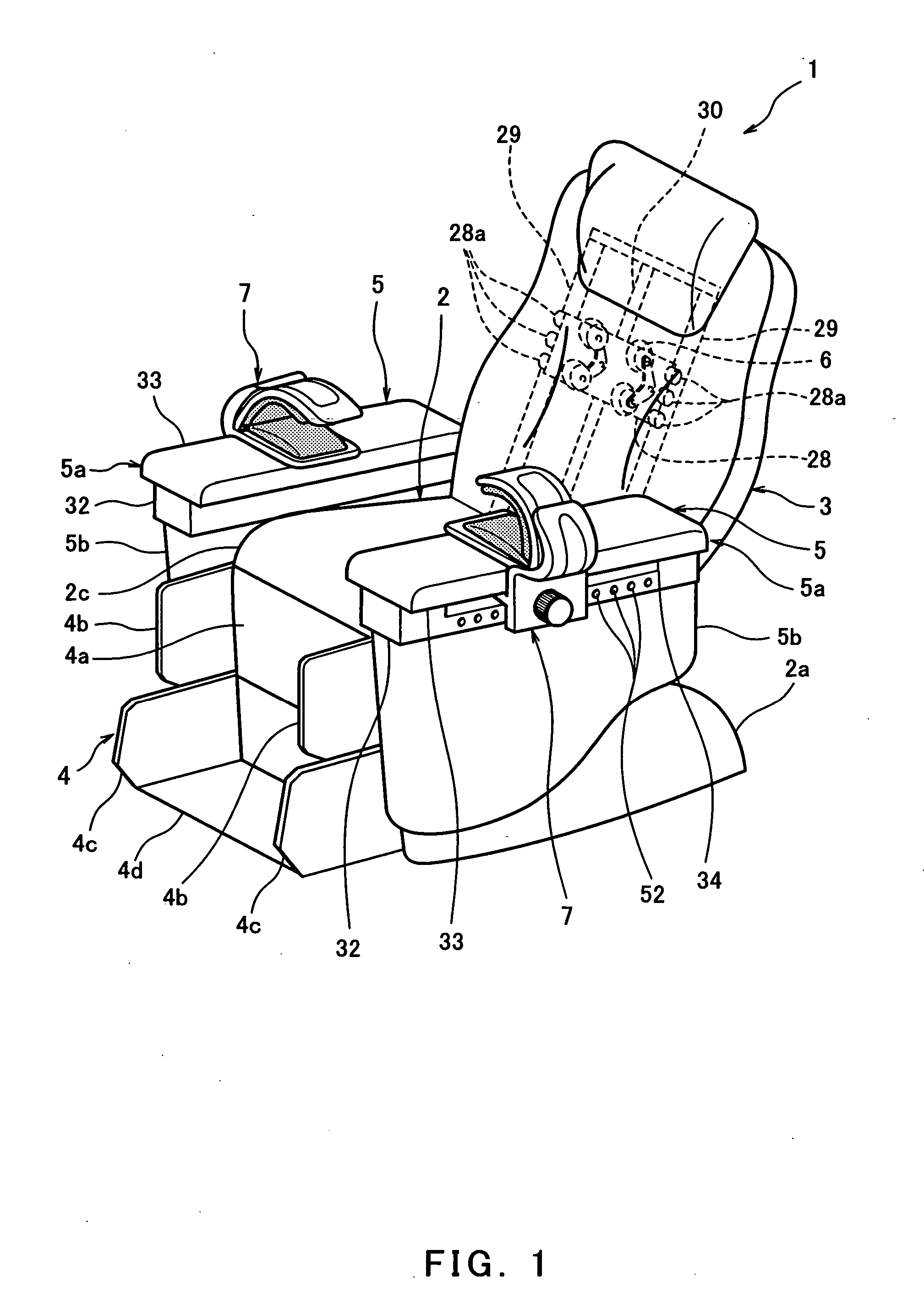
[0122]FIG. 1 is a perspective view illustrating the entire construction of a massaging apparatus according to embodiment 1 of the present invention. As shown in FIG. 1, the massaging apparatus according to embodiment 1 is the chair type one and is configured to mainly include a seat 2, a backrest 3, a footrest 4, and armrests 5. The seat 2 is configured such that a base (not shown) having at both lower sides thereof leg portions 2a has at the upper part thereof a cushion portion 2c. The cushion portion 2c is provided to have a substantially flat upper face that is used as a seating surface. The cushion portion 2c is configured such that an inner packing material (not shown) made of urethane foam, sponge, or polystyrene foam is provided at the upper face of the base and the inner packing material is covered by an outer packaging material (cover) formed of polyester-made raised tricot, synthetic leather, natural leather or the like.

[0123] In the following description, the expression ...

embodiment 2

[0158]FIG. 9 is a partial cross-sectional front view illustrating a forearm massager according to embodiment 2 of the present invention. As shown in FIG. 9, an armrest 55 of the massaging apparatus according to embodiment 2 has, at the outer face (i.e., right side face in the case of the right side armrest 55 or left side face in the case of the left side armrest 55, respectively), a groove 56 extending forward and backward. A support portion 57 for supporting the forearm of the user while having a contact thereto is provided above the groove 56. The support portion 57 is rounded and substantially rectangular plate-shaped. A round bar-like guide rail 56a is provided between the front and rear end faces of the groove 56 (not shown). The guide rail 56a penetrates, with an appropriate play, the substantially cuboid-like detachable member 58 having a size that can be loosely fitted with the groove 56. This allows the detachable member 58 to move along the guide rail 56a for the entire l...

embodiment 3

[0165]FIG. 10 is a perspective view illustrating the construction of a forearm massager according to embodiment 3 of the present invention. FIG. 11 is a partial cross-sectional front view thereof. FIG. 12 is a partial cross-sectional front view illustrating the construction of an armrest when the forearm massager according to embodiment 3 of the present invention is not attached. As shown in FIG. 10, in a base 63a of the armrest 63 according to embodiment 3, a portion forward of the protruding portion 36a is lacked to provide a stepped portion 64a having a substantially horizontal surface and an attachment face 64b that is continued from the stepped portion 64a and that has a substantially vertical face (see FIG. 11). The protruding portions 36a and 36b have a threaded rod 65 in parallel with the guide rail 37. The threaded rod 65 is supported by bearings (not shown) at the respective protruding portions 36a and 36b so as to be rotatable around a center axis. The threaded rod 65 als...


PUM


Abstract

The present invention is aimed at providing a chair-like massaging apparatus and a forearm massager for use with the chair-like massaging apparatus, which are capable of massaging a forearm of a user as desired and allow the user to take a free posture because of absence of an arm obstructing part in an upper portion of an armrest when the forearm is not to be massaged.
To this end, the massaging apparatus of the present invention is configured such that an arm rest (5) configured to support a forearm of the user is provided with a detachable member (38) that is movable along a guide rail (37) and the detachable member (38) is provided with a fitting groove (39). A forearm massager (7) configured to be capable of giving pressure stimulation to the forearm with the forearm of the user sandwiched between the fix and support portion (46) and the pressing portion (47) is provided with a fitting protrusion (40) fitted in the fitting groove (39). By removably fitting the fitting protrusion (40) into the fitting groove (39), the forearm massager (7) is removably attached to the armrest (5).

Description

TECHNICAL FIELD [0001] The present invention relates to a massaging apparatus configured to massage a forearm of a user and a forearm massager for use with the massaging apparatus. BACKGROUND ART [0002] One of conventional chair type massaging apparatuses by which a forearm of a user can be massaged is disclosed in Japanese Laid-Open Publication No. 2001-204776. The massaging apparatus disclosed in the publication has, at the upper part of the armrest, an arm holding portion comprising a holding wall portion forming a U-shaped concave portion. This holding wall portion includes an air bag. Compressed air is supplied to or exhausted from the air bag in each holding wall portion so that the air bag is expanded or contracted. As a result, an arm (forearm) of the user inserted into the concave portion of the holding wall portion is massaged by providing pressure and releasing the pressure to the arm in a sandwiching manner. [0003] Another conventional massaging apparatus is disclosed in...

Claims


Application Information

Patent Timeline
IPC IPC(8): A61H7/00A61H15/00A61H1/00A61H23/02A61H23/04A61H37/00A61H39/04
CPCA61H7/001A61H2201/5066A61H9/0078A61H15/0078A61H23/0254A61H2015/0014A61H2015/0028A61H2201/0149A61H2201/0207A61H2201/0228A61H2201/1669A61H2205/06A61H2205/081A61H2205/10A61H2205/12A61H7/007A61H2201/1427A61H2201/1604A61H2201/1623A61H2201/1628A61H2201/1635A61H2201/164A61H2201/1654A61H2201/1678A61H7/004A61H7/00A61H15/00A61H39/04
Inventor FUJII, YASUOINADA, NICHIMU
Owner FAMILY INADA
Why Eureka
Try Eureka