Inter-authentication method and device

a technology of authentication method and authentication method, applied in the field of authentication method and device, can solve the problems of inability of third parties inability to ensure the security of future oids, and inability to predict the next oid conveniently, so as to reduce the number of communication times, enhance the security of communication, and improve the convenience

Inactive Publication Date: 2006-06-29
PSD +1
View PDF1 Cites 176 Cited by
  • Summary
  • Abstract
  • Description
  • Claims
  • Application Information

AI Technical Summary

Benefits of technology

[0082] Therefore, it is possible to develop resistance to DoS attack, spoofing and the like, and even under an open network environment, ID information can be protected and security in communication can be enhanced. Further, remote accessing becomes available, and convenience can be improved.
[0083] In the present invention, as one-way function Fc used for determining validity of the first device, a pseudo-random number function is utilized in which a predefined shared key, one of Diffie-Hellman public values, ID predefined in the first device and the onetime ID are used as arguments, and as one-way function Fs used for determining validity of the second device, a pseudo-random number function is utilized in which a predefined shared key, the other of Diffie-Hellman public values, ID predefined in the second device and the onetime ID are used as arguments. Therefore, it is possible to reduce number of communication times to twice, which has been required to be three times in a conventional key exchange and authentication method, and a rapid and safe authentication, and key exchange can be achieved.
[0084] In the present invention, authentication between devices (between a client and a server) is carried out by use of a onetime ID, which is generated by various onetime ID generating methods as the following: a variable shared key which changes per communication unit is generated, a function value of one-way function is obtained in which the variable shared key is used as an argument, a onetime ID is generated from the function value; a variable shared key is generated, a function value of one-way function is obtained in which the variable shared key and information regarding a communication sequence are used as arguments, a onetime ID is generated from the function value, and a predefined variable shared key is generated between devices or applications; and a random number is generated within a predefined communication unit, a function value of one-way function is obtained in which the random number and the shared key are used as arguments, and a onetime ID is generated from the function value. Therefore, there is an effect that generating a onetime ID hard to tap and superior in security is possible, and a future security (PFS: perfect forward secrecy) of the onetime ID can be achieved.

Problems solved by technology

In addition, the user has to pay attention to safekeeping of the key, and the key cannot be used conveniently.
Further, it is impossible for the third party to predict a next OID, since the OID is changed every time communication is made between the client and the server, i.e., every time when SA is generated and updated.
Consequently, there has been a problem that a security for future OIDs (in other words, PFS: Perfect Forward Security) cannot be assured.
Therefore, there is also a similar problem as described above.

Method used


Image

  • Inter-authentication method and device
  • Inter-authentication method and device
  • Inter-authentication method and device

Examples


example 1

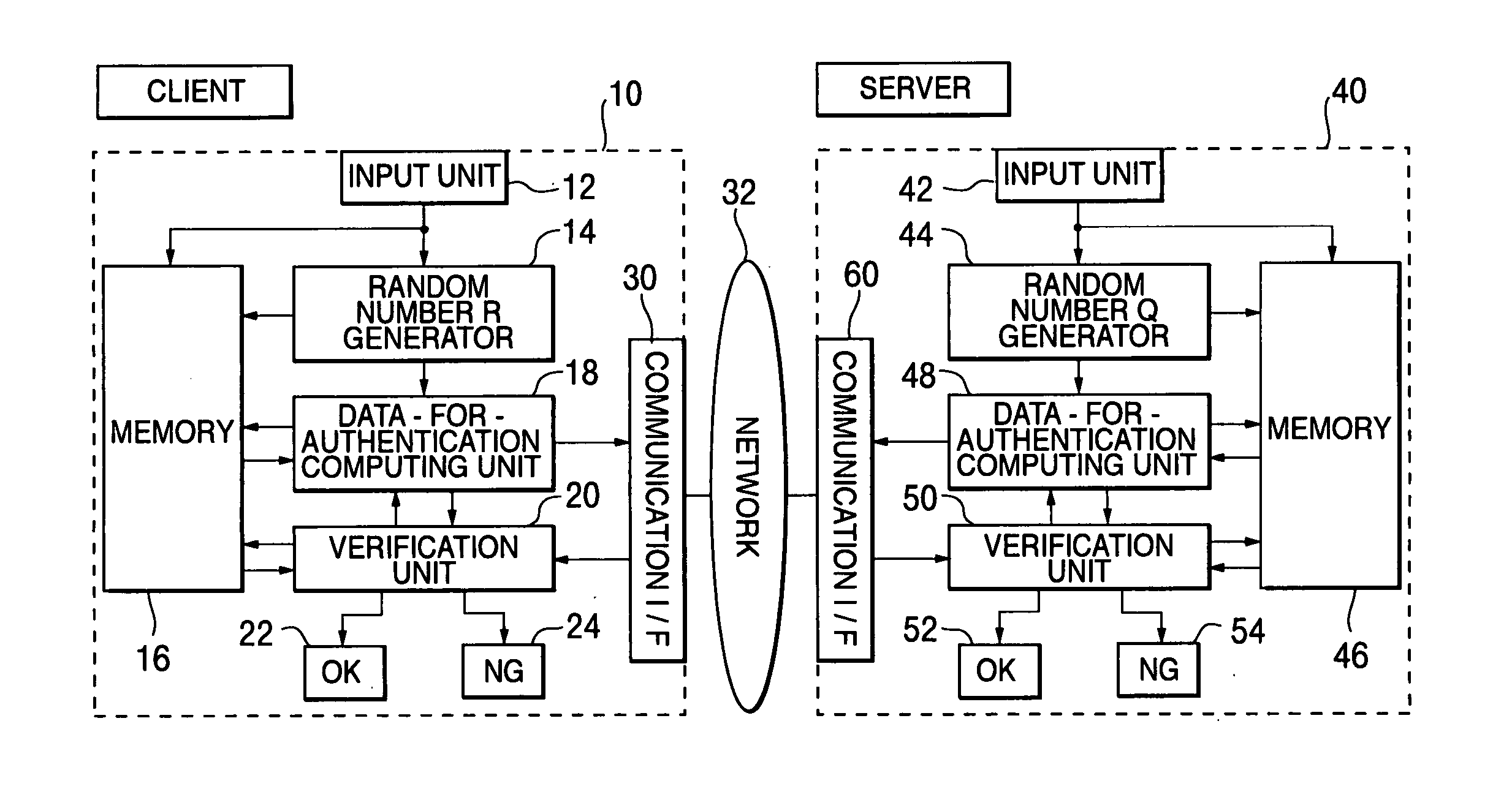
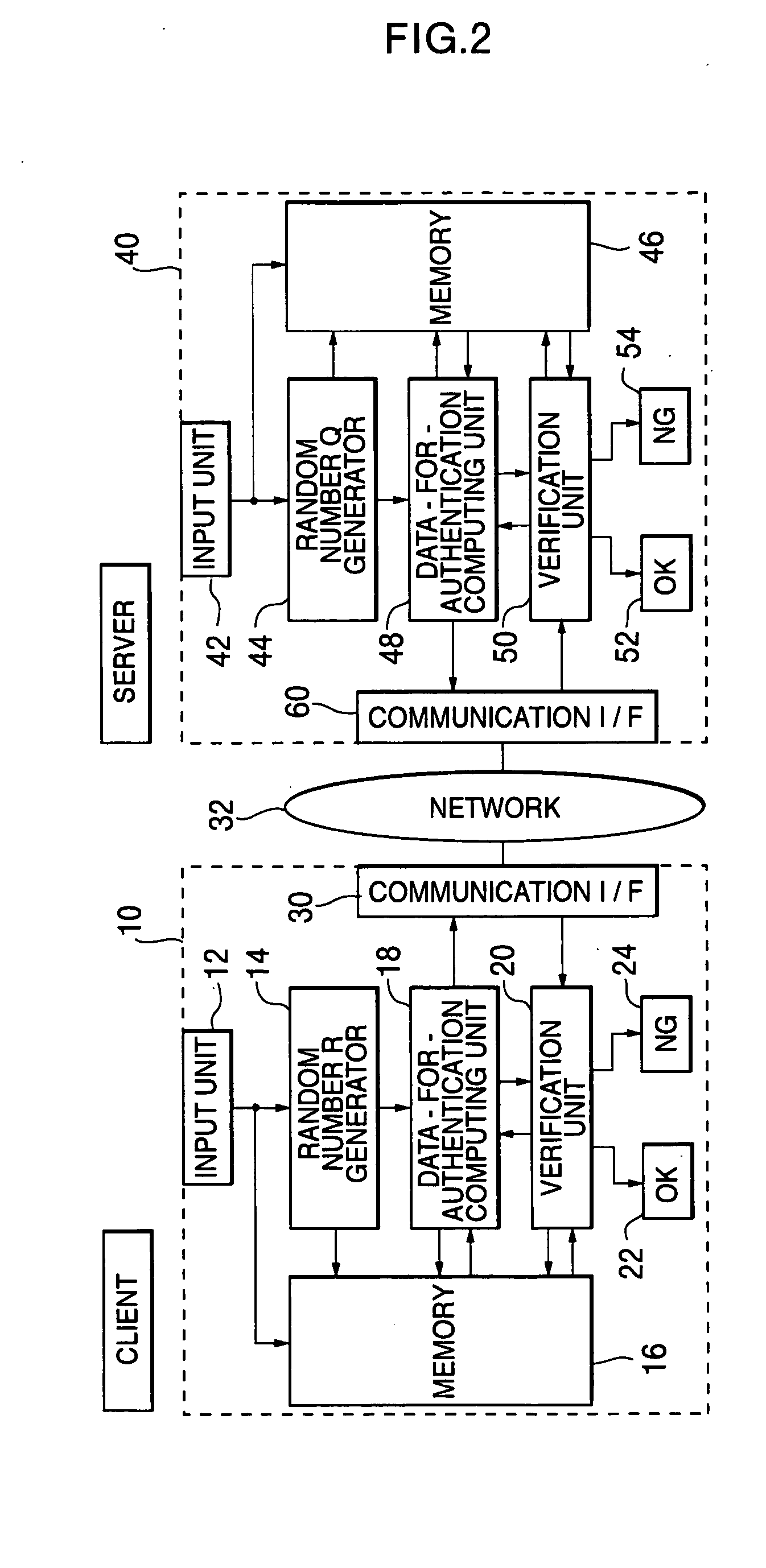
[0104] Hereinafter, one example of the preferred embodiments of the present invention will be explained in detail referring to the attached drawings. FIG. 2 is a block diagram showing a schematic configuration of a client computer and a server computer concerning the first embodiment of the present invention, and a schematic configuration of a network system to which the present invention can be applied. The first embodiment represents an application of the present invention to a case of mutual authentication between the server computer and the client in a network.

[0105] In FIG. 2, the network system is configured by one or a plurality of client computers 10 including at least CPU and one or a plurality of server computers 40 including at least CPU, which are connected to the network (for example, the Internet) 32, respectively via modems, routers, TAs (Terminal Adapters) and the like. These computers can give and receive information with each other by the mutual communication via ...

example 2

[0182]FIG. 5 is a schematic configuration which shows the second embodiment of the authentication system concerning the present invention. The authentication system is schematically configured by a server (the second device) 10 and a client (the first device) 20, which are mutually connected via a network 40 such as a public circuit network and the Internet. In the present embodiment, a plurality of servers A, B, C . . . for providing various services are connected to the server 10, and the server 10 functions as an authentication server to determine whether or not accessing to the servers A, B, C . . . is possible.

[0183] As shown in FIG. 6, the server 10 is configured by CPU 11, RAM 12, storage unit 13, input unit 14, display unit 15 and communication unit 16 and the like, and each part is connected via bus 17.

[0184] The CPU (Central Processing Unit) 11 stores in the RAM 12 various programs stored in the storage area of the storage unit 13, various instructions inputted from the ...

example 3

[0214] In the second embodiment as described above, a function value of a hash function is obtained, in which the encryption key (variable shared key) generated in the previous session is used as an argument, and this function value is used as onetime ID (SIGNAL) of the current session. In the third embodiment, a function value of the hash function is obtained, in which the shared key generated in the previous session and a communication sequence in the current session are used as arguments, and this hash function value is used as a onetime ID in each communication timing of the current session. The third embodiment is similar to the second embodiment besides a part peculiar to the third embodiment. In the third embodiment, same reference numbers are given to the parts same as those of the second embodiment, and the descriptions thereof will be omitted.

[0215]FIG. 9 is a diagram which explains the third embodiment of the authentication method concerning the present invention. In the...


PUM


Abstract

An objective of the present invention is to obtain a mutual authentication method in which mutual authentication is carried out securely and conveniently. In order to achieve the above objective, in the mutual authentication process, a private key K0, being an initial value, is stored in a client and a server (Pc0, Ps0). The client generates a random number R, calculates secret data C and authentication data A, and transmits the data items to the server (Pc1). The server receives the authentication data A and the secret data C from the client, and generates a random number Q, calculates secret data S, and authentication data B and returns the data items, as well as updating the private key K0 with a private key K1 (Ps1). The client receives from the server the authentication data B and the secret data S, generates the random number R, calculates secret data C2, authentication data A2, and returns the data items to the server, and updates the private key K0 with the private key K1(Pc2). The client and the server check whether or not validity is established (Psm+1, Pcm+1). Further in the authentication method above, there is a method for generating a onetime ID, assuming that the onetime ID is identification information usable just one time in the authentication between a plurality of devices or application. In each of the devices or applications which carries out the authentication, a variable shared key which changes per predefined communication unit requiring the authentication is generated, a function value of one-way function is obtained in which the variable shared key is used as an argument, a onetime ID hard to tap and superior in security is generated based on the function value, and the onetime ID is utilized.

Description

BACKGROUND OF THE INVENTION [0001] 1. Field of the Invention [0002] The present invention relates to an inter-authentication method and device, more specifically, the present invention relates to a mutual authentication method and apparatus in a computer system and the like, being connected to a network, a method for generating onetime ID used therein, an authentication method, an authentication system, server, client and program. [0003] 2. Description of the Related Art [0004] More particularly, the present invention relates to a mutual authentication method and an apparatus for checking validity as to a relationship at least between a first authentication device and a second authentication device, a method for generating onetime ID which is suitable for being used in authentication between a plurality of devices or applications, an authentication method, authentication system, server, client and program, utilizing the onetime ID. [0005] Authentication is required for a user to pro...

Claims


Application Information

Patent Timeline
Patent Type & Authority Applications(United States)
IPC IPC(8): H04L9/00H04L9/32H04L29/06
CPCH04L9/3273H04L63/067H04L63/0869H04L9/0891
Inventor IMAMOTO, KENJIOKAWA, KATSUYOSHIHASHIMOTO, TSUTOMU
Owner PSD
Why Eureka
Try Eureka