Liquid separator for vacuum filter

a vacuum filter and liquid separator technology, applied in the direction of cleaning filter means, cleaning equipment, separation processes, etc., can solve the problems of many seal structures, contaminating the environment, and the vacuum system is reduced to not pulling an adequate vacuum to properly

Inactive Publication Date: 2006-07-06
CHARLES G AGERLID
View PDF4 Cites 17 Cited by
  • Summary
  • Abstract
  • Description
  • Claims
  • Application Information

AI Technical Summary

Benefits of technology

[0008] A cage, having an upper end extending into one of said arcuate slots has an inner cylindrical filter chamber communicating with the annular outer filter chamber in the cylindrical enclosure and a float valve is movably mounted in said inner filter chamber in said cage, said float valve having a generally cylindrical shaped outer surface encircling a skirt portion and a generally cylindrical shaped inner surface encircling an air chamber. The air chamber is filled with air or other gas to assist in controlling the buoyancy of the float valve. The float valve must be light enough to float in liquid collected in the filter chamber but heavy enough to prevent it from being prematurely drawn upwardly by the flow of air through the system.
[0010] A seal is provided on said cap adjacent the lower end of said central air chamber, said inclined conical sealing surface on said float valve moving into sealing relation with said seal when liquid accumulates in said outer filter chamber, said float valve being configured to float in accumulating liquid and to prevent the float valve being lifted by air flow through said inner filter chamber in said cage toward said central air chamber.

Problems solved by technology

If the filtration elements are heavily clogged with sediment silt and process debris the vacuum system is reduced to not pulling an adequate vacuum to properly vacuum pack food and other product ingredients to provide proper protection from deterioration.
Further, debris and sediment passed through a filter to a vacuum pump and some through the pump can possibly contaminate the environment where sanitation considerations are quite important.
Furthermore, it is also important that vacuum system filter systems be cleaned of food debris often enough that undesired spoilage and bacteria growth are kept under control and the vacuum system is up to health and safety standards at all times. With frequent filter disassembly and reassembly for filter cleaning and servicing seal wear and damage can be and in many seal structures is a serious problem.
However, a hollow plastic ball is not aerodynamically shaped to form a suitable float valve in a system in which the flow rate of air is several hundred cubic feet per minute through a constricted area.
The ball was drawn by rapidly moving air into outlet ports prematurely.

Method used


Image

  • Liquid separator for vacuum filter
  • Liquid separator for vacuum filter
  • Liquid separator for vacuum filter

Examples


Embodiment Construction

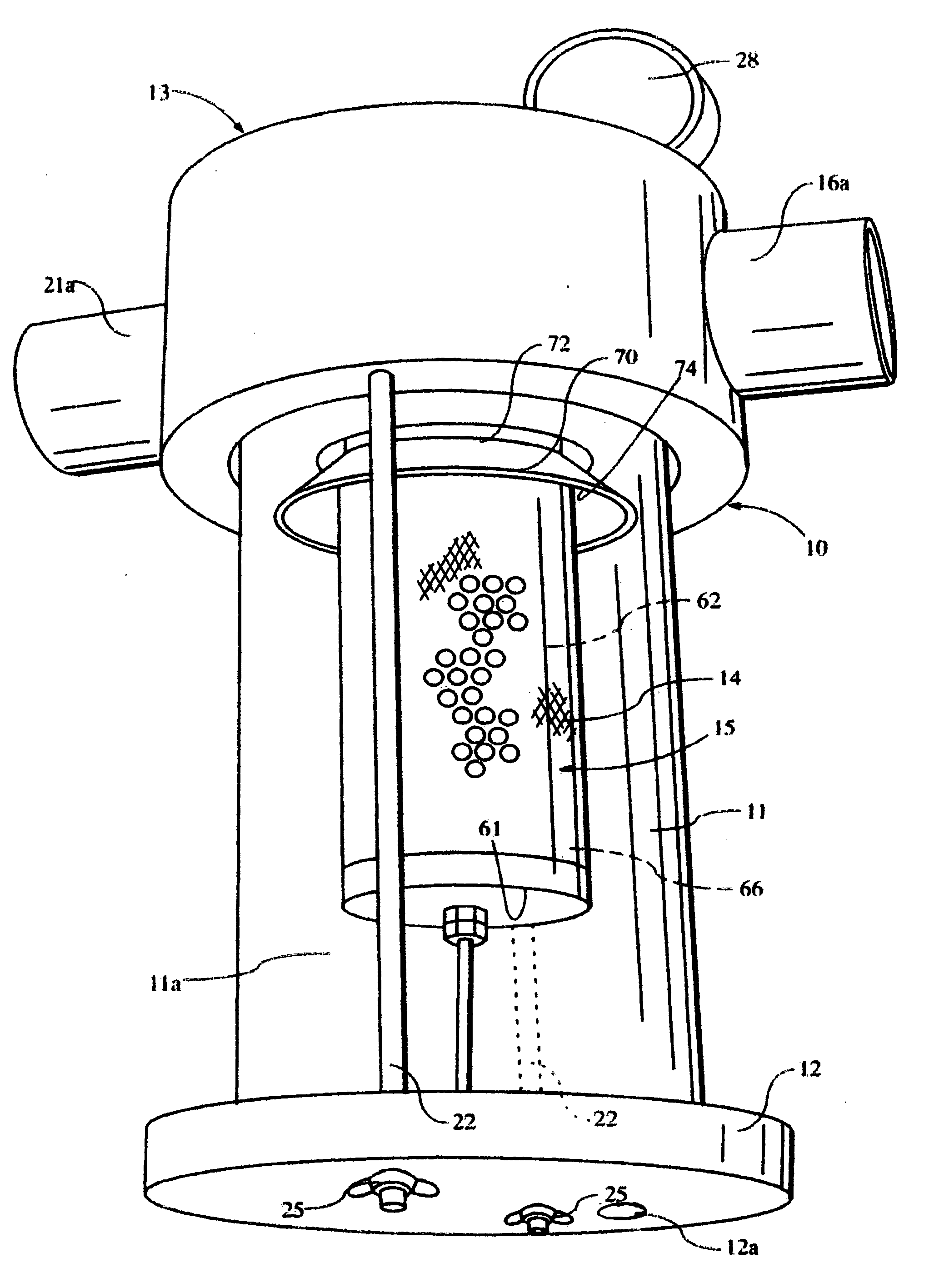
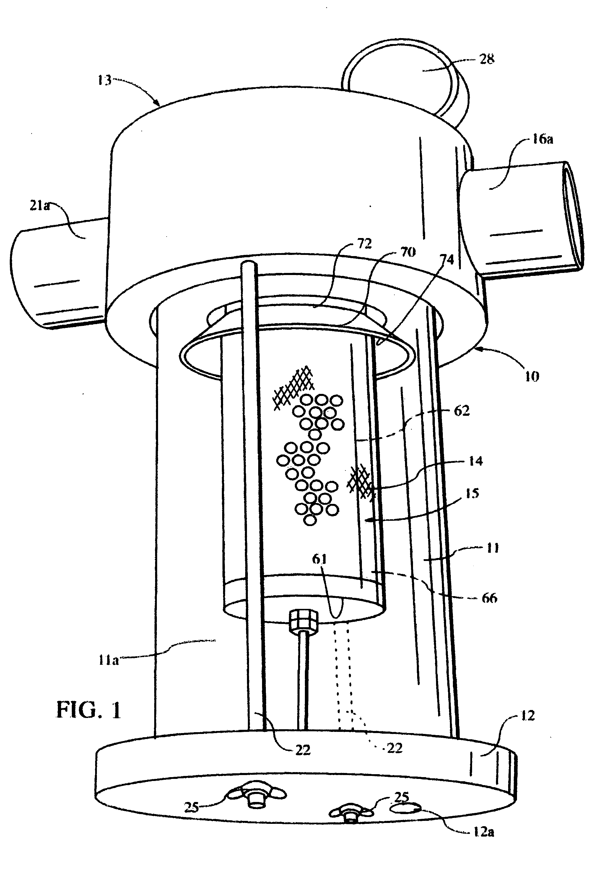
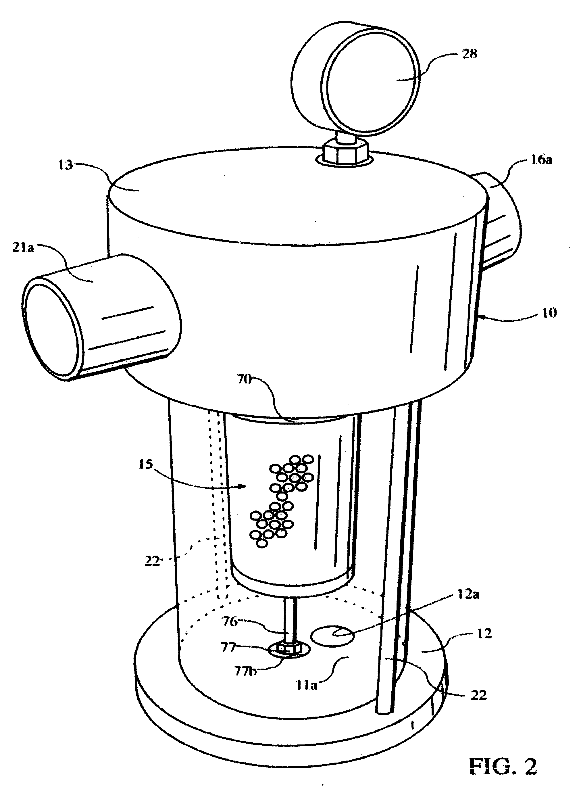
[0019] Referring to FIGS. 1 and 2 of the drawing, the numeral 10 generally designates a vacuum filter having a transparent outer cylindrical enclosure member 11 extending between a bottom filter plate 12 and a top filter cap 13. Enclosure member 11 has indicia 11a on the surface which reads, for example, “Stop Vacuum Pump, Drain Liquid at This Level,” to warn operators that water or other liquid should be drained by opening a drain valve (not shown) in passage 12a.

[0020] The top filter cap 13 has a threaded air inlet opening 16, that is connectable to a vacuum pack machine through an air line (not shown), communicating through an arcuate passage 17 between the transparent outer cylindrical enclosure member 11 and the outer surface of a cylindrical filter screen 14. Top filter cap 13 also has a center air chamber 19, that is an upper extension of an inner cylindrical filter chamber 20 within an inner liquid separator assembly 15, and therefrom a threaded air outlet opening 21 that i...


PUM

PropertyMeasurementUnit
angleaaaaaaaaaa
heightaaaaaaaaaa
diameteraaaaaaaaaa

Abstract

A float valve 80, made of HDPE, is movably mounted in a stainless steel cage 60 in an in-line vacuum filter. The float valve has a chamber 85 formed in a skirt portion 84 thereof. Float valve 80 has a generally cylindrical shaped outer surface 82 encircling the skirt portion 84 and a generally cylindrical shaped inner surface 83 encircling the chamber 85. A upper portion 86 extends across the upper end of valve 80 to form an inverted cup shaped body. The upper portion 86 extending across the upper end of said valve 80 has a threaded hole 87 formed therein to receive a threaded bolt 88 for forming a ballast to permit adjustment of the weight of said valve 80 so that it floats at a level that prevents it being drawn by venturi effect into the central air chamber 19 before a predetermined volume of liquid is collected in the cylindrical enclosure 11 through which air flows en route to the filter element 14. The water line is about 1 inch above the bottom edge of the skirt portion 84 and about 1 inch below the sealing surface 95 to assure that the float valve will engage a seal 98 on said cap 13 adjacent the lower end of central air chamber 19 before liquid is drawn into air chamber 19. The chamber 85 forms an air pocket in which air is trapped to lift the float valve 80 for positioning the sealing surface 95 a predetermined distance above the surface of water or other liquid in which it is floating.

Description

TECHNICAL FIELD [0001] The invention relates to apparatus for removing and collecting droplets of water or other liquid in an in-line vacuum filter. BACKGROUND OF INVENTION [0002] This invention relates in general to air flow filter devices, and more particularly, to an industrial type in-line outer to inner flow vacuum filter with a transparent outer cylindrical enclosure so that a machine operator can easily see when it is time to disassemble and clean the filter of sediment and process debris buildup thereon equipped with “O” ring seals that are loose in the relaxed state facilitating repeated filter disassembly and reassembly yet subject to being drawn into the sealing state when a vacuum is drawn in the filter. [0003] This application relates to improvements in devices of the type disclosed in U.S. Pat. No. 4,544,387, issued Oct. 1, 1985, to Charles G. Agerlid, entitled “Outer To Inner Flow Vacuum Filter With See Through Outer Enclosure,” the disclosure of which is incorporated...

Claims


Application Information

Patent Timeline
Patent Type & Authority Applications(United States)
IPC IPC(8): A47L9/10
CPCB01D45/04B01D46/0005B01D46/003B01D46/2411B01D46/4272
Inventor AGERLID, CHARLES G.AGERLID, CHRISTOPHER
Owner CHARLES G AGERLID
Why Eureka
Try Eureka