Apparatus for continuously aspirating a fluid from a fluid source

a technology of fluid source and apparatus, which is applied in the direction of liquid handling, instruments, packaged goods types, etc., can solve the problems of operators being exposed to potentially infectious or harmful fluid materials

Active Publication Date: 2006-07-06
MDTECH
View PDF21 Cites 23 Cited by
  • Summary
  • Abstract
  • Description
  • Claims
  • Application Information

AI Technical Summary

Benefits of technology

[0007] It is another object of this invention to provide an apparatus for collecting the aspirated fluid at a remote location without the need for operator contact or exposure to potentially dangerous or harmful fluid materials.
[0008] It is yet another object of this invention to provide an internally mounted shut-off valve to monitor the fluid collection for overflow while eliminating the need for operator action, whereby operator contact with or exposure to potentially dangerous or harmful fluid materials is prevented.
[0009] The above and other objects of this invention can be attained through an apparatus for continuously aspirating a fluid from a fluid source. The apparatus includes a first container forming a chamber. A vacuum source is operatively connected to the first container and includes a first vacuum tube exposed to or extending into the chamber. A first level sensor is positioned within the chamber to monitor a fluid level within the chamber. A first fluid collection tube extends into the chamber and is operatively connectable to an aspirator device, thereby providing communication between the fluid source and the chamber. A first solenoid valve connects the first container to the vacuum source, and is activatable to provide communication between the vacuum source and the chamber. A relay is in electrical communication with the first solenoid valve and activates the first solenoid valve to move to an open position. With the first solenoid valve in the open position, a vacuum is exposed within the chamber to aspirate at least a portion of the fluid from the fluid source to within the chamber. A first shut-off valve is positioned within the chamber and prevents communication between the vacuum source and the chamber with a fluid level within the chamber at a fluid level setpoint.

Problems solved by technology

This process requires operators to handle the fluid, thereby subjecting the operators to potentially infectious or harmful fluid materials.
External shut-off valves further subject operators to potentially infectious or harmful fluid materials.

Method used


Image

  • Apparatus for continuously aspirating a fluid from a fluid source
  • Apparatus for continuously aspirating a fluid from a fluid source
  • Apparatus for continuously aspirating a fluid from a fluid source

Examples


Embodiment Construction

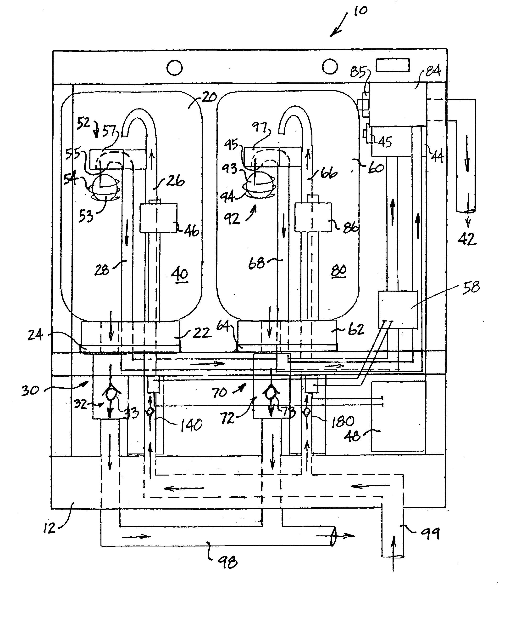
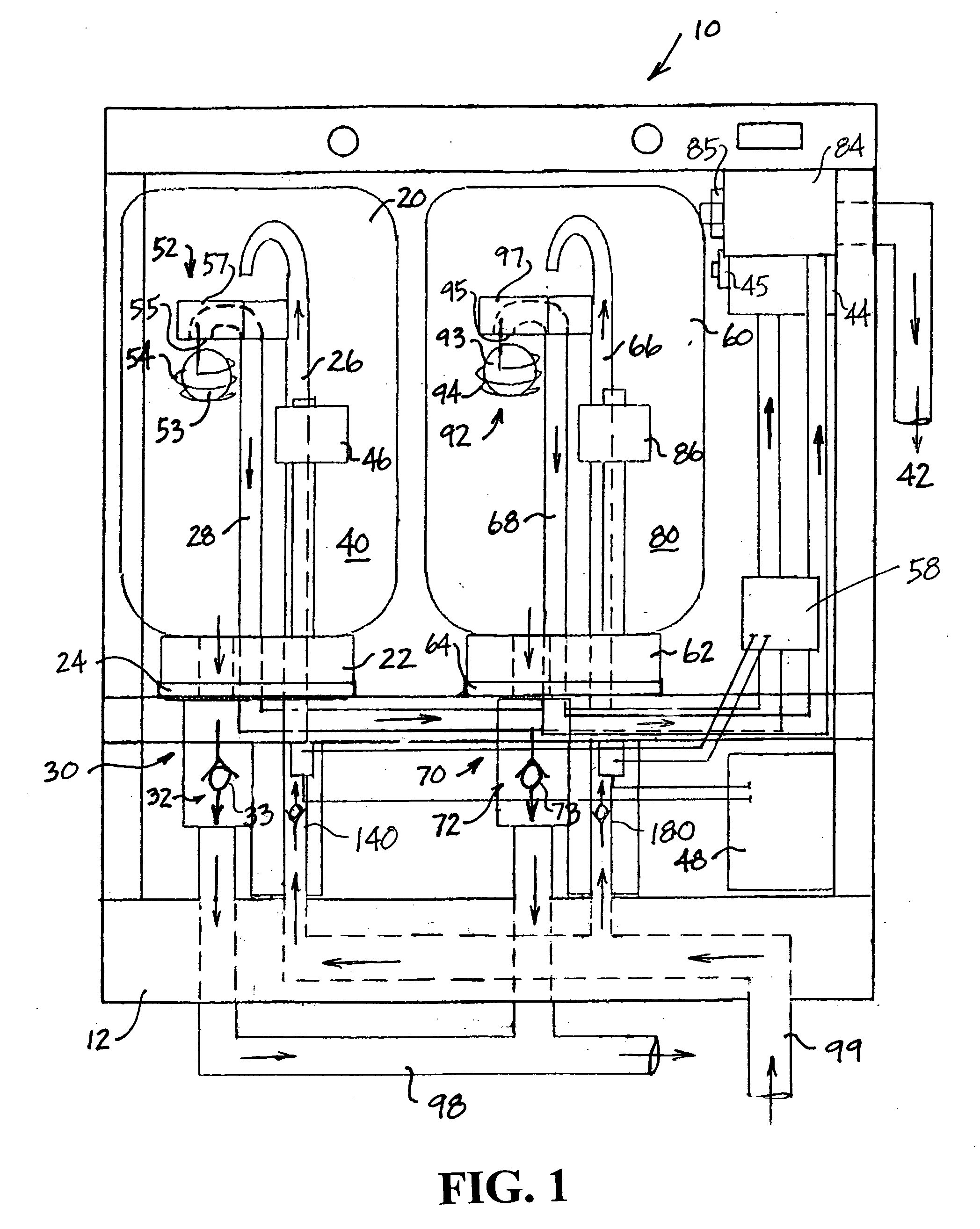
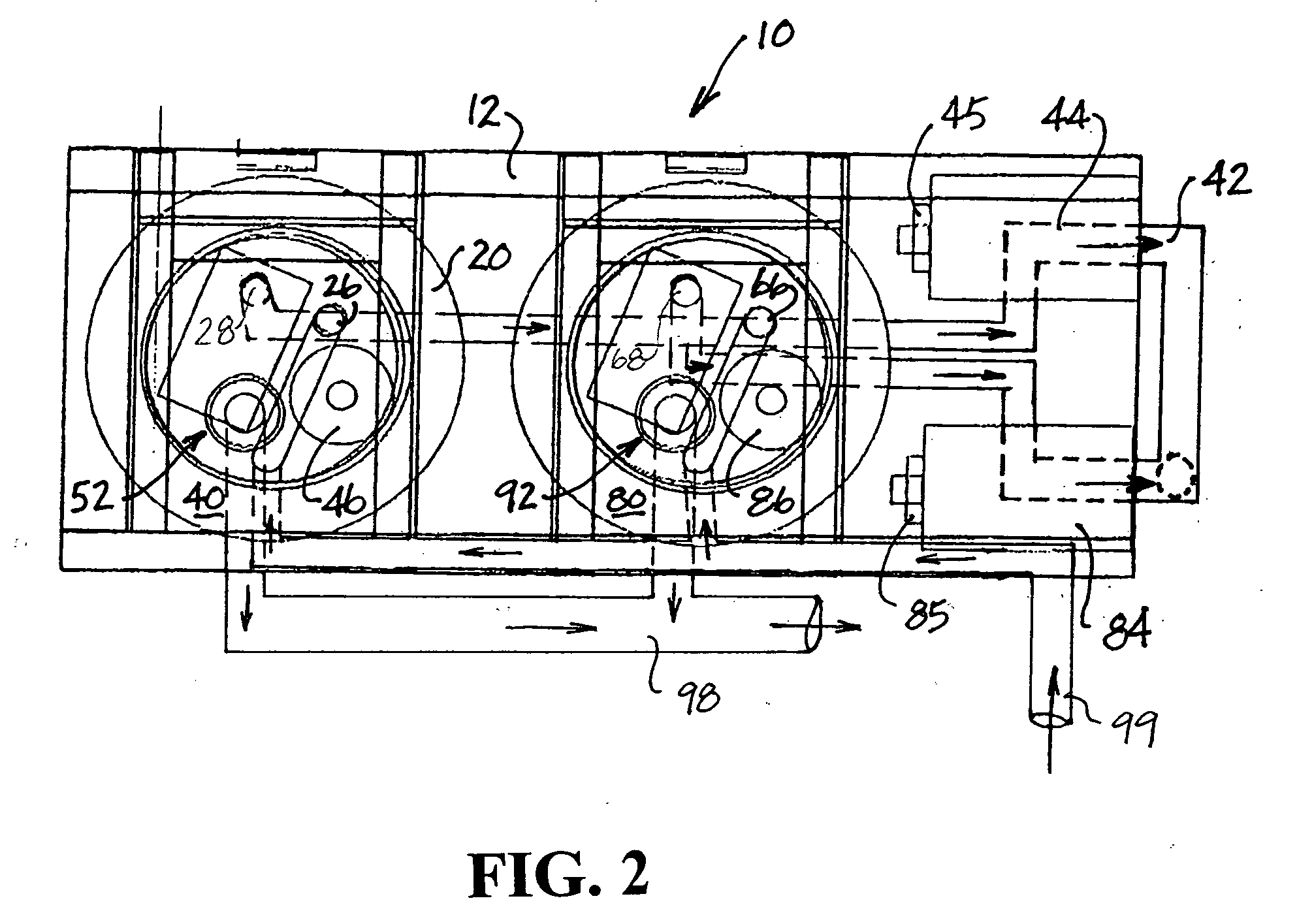
[0016] This invention provides an apparatus for aspirating a fluid from a fluid source. Suction is employed to collect the fluid within one or more containers and, by interrupting the suction within a selected container, the collected or aspirated fluid can be drained through a drain pipe to a remote site. Preferably, the apparatus includes a plurality of containers that can be selectively filled with aspirated fluid collected from the fluid source. As one container is used to collect the aspirated fluid, the aspirated fluid collected in another container is drained to the remote site, thus, providing an apparatus and method for continuously aspirating a fluid from a fluid source. For example, the apparatus can be used with a medical instrument or tool, such as an endoscope, to remove bodily fluids, including small particles, from an internal area of an animal body or a human body.

[0017] Referring to FIGS. 1-3, apparatus 10 for continuously aspirating a fluid from a fluid source in...


PUM

PropertyMeasurementUnit
vacuumaaaaaaaaaa
suctionaaaaaaaaaa
flexibleaaaaaaaaaa

Abstract

An apparatus for continuously aspirating a fluid from a fluid source. A vacuum source is operatively connected to a first container forming a first chamber and a second container forming a second chamber. A fluid collection tube provides communication between the fluid source and each of the first chamber and the second chamber. A first level sensor is positioned within the first chamber and a second level sensor is positioned within the second chamber. Upon receiving a signal generated by one of the first level sensor and the second level sensor, a relay responsively exposes a vacuum within one of the first chamber and the second chamber to continuously aspirate at least a portion of the fluid from the fluid source. A shut-off valve is preferably positioned within each of the first chamber and the second chamber to prevent communication between the vacuum source and the corresponding chamber with a fluid level within the chamber at a fluid level setpoint.

Description

BACKGROUND OF THE INVENTION [0001] 1. Field of the Invention [0002] This invention relates to an apparatus and method for continuously aspirating a fluid from a fluid source. [0003] 2. Discussion of Related Art [0004] During surgical procedures, a medical instrument, for example an endoscope, may be inserted into an interior area of the patient's body to remove bodily fluids, which may contain potentially infectious or harmful fluid materials. These fluids, which may include small particles, are drawn through the instrument and are collected within a container using a vacuum or suction source. In many conventional apparates, when the container is filled, the procedure is interrupted in order to empty the container of the collected fluid. Typically, the collected fluid is deposited locally within a larger container. After the container has been emptied, the procedure can continue until the container is once again filled. This process requires operators to handle the fluid, thereby su...

Claims


Application Information

Patent Timeline
Patent Type & Authority Applications(United States)
IPC IPC(8): B67C3/16
CPCA61M1/0049A61M2205/3382Y10T137/469Y10T137/2534Y10T137/0318Y10T137/3109A61M1/782
Inventor MERKLE, WILLIAM L.
Owner MDTECH
Why Eureka
Try Eureka