Wheel chock restraint system

a technology of restraint system and chock, which is applied in the field of wheel chock restraint system, can solve the problems of not being designed to resist, trucks that cannot be secured by such icc bars, hazardous loading and unloading operations, etc., and achieves the effects of convenient and effortless handling, convenient proper placement of the chock, and easy manipulation of the chock

Inactive Publication Date: 2006-07-06
9172 9863 QUEBEC
View PDF16 Cites 17 Cited by
  • Summary
  • Abstract
  • Description
  • Claims
  • Application Information

AI Technical Summary

Benefits of technology

[0010] The primary object of the present invention is a wheel chock restraint system provided to restrain the movement of a vehicle away from a loading dock during loading and unloading operations. The system comprises a wheel chock having an engagement means adapted to cooperate with a corresponding engagement means of a support plate mounted on the ground. The chock is attached to a movable arm attached to the loading dock and adapted to assure secure positioning of the chock under the wheel of the truck. The arm is provided with a tension means facilitating easy manipulation of the chock and placing the arm into the storage position.
[0013] Still another object of the present invention is to prevent solid jamming of the chock by means of a locking element keeping a slight distance between the wheel and the chock.

Problems solved by technology

Loading and unloading operations are hazardous for fork lifts entering and exiting the truck trailer.
However, while the first system is suitable for a majority of trailers, there are several configurations of trucks that cannot be secured by such ICC bars.
Besides, ICC bars are built to absorb a rear impact with another truck and are not designed to resist a strong pulling force.
In view of this fact, this system does not prevent the truck from moving away from the loading dock.
Manual placement of a chock presents different problems, such as: chocks may be displaced, damaged, lost, or stolen.
They also may slip on icy, oily or dusty surfaces and are often difficult to remove from their operational position because they may be wedged very tightly under the trailer's wheel.
Very often, chocks are removed before the loading operation is complete, thus creating a dangerous situation where the vehicle can depart prematurely or slide away from the dock as heavy fork lifts enter the trailer.
Also, docked trailers can be stolen mostly after business hours.
Often, standard chocks are placed too far from the wheel to be effective because they can jam and become very difficult to remove; for example, when an empty trailer becomes heavily loaded, the weight on the tires makes them extend sideways, resulting in the wheel to sit on the chock.
A tire can also jam into the chock if the air ride suspension causes a slight movement of the trailer when depressed.
However, they may be buried in the driveway during installations under ground, are expensive to install, require a drainage system to prevent them to be filled with water.
They also are not very easy to service and have to travel a substantial distance from storage into operative position.
Other mechanical chocks which are mounted on the surface may be affected by winter and become an obstacle during snow removal They may interfere with the tail gate of the truck or truck's undercarriage, and are inoperable with many types of vehicles.
The major disadvantage of said system was its effective range: because the spring was attached to the rear arm, the more said arm was extended, the more tension was created in the spring making the handling of said the chock attached to said arm harder and harder after 7 feet of extension of the arm from the loading dock.
At the distance of 10 to 14 feet, handling the arm required a great deal of effort and force.

Method used


Image

  • Wheel chock restraint system
  • Wheel chock restraint system
  • Wheel chock restraint system

Examples


first embodiment

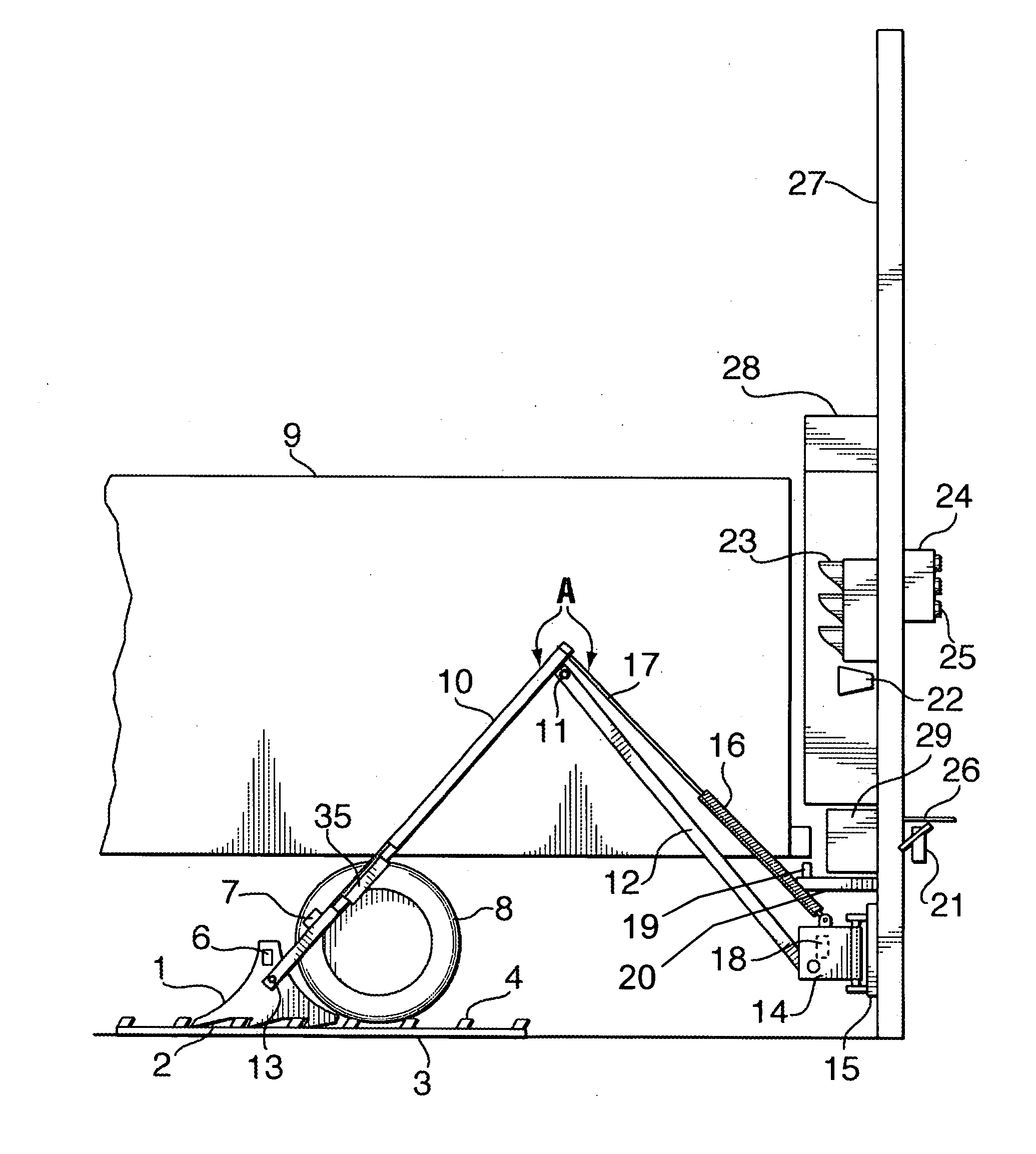
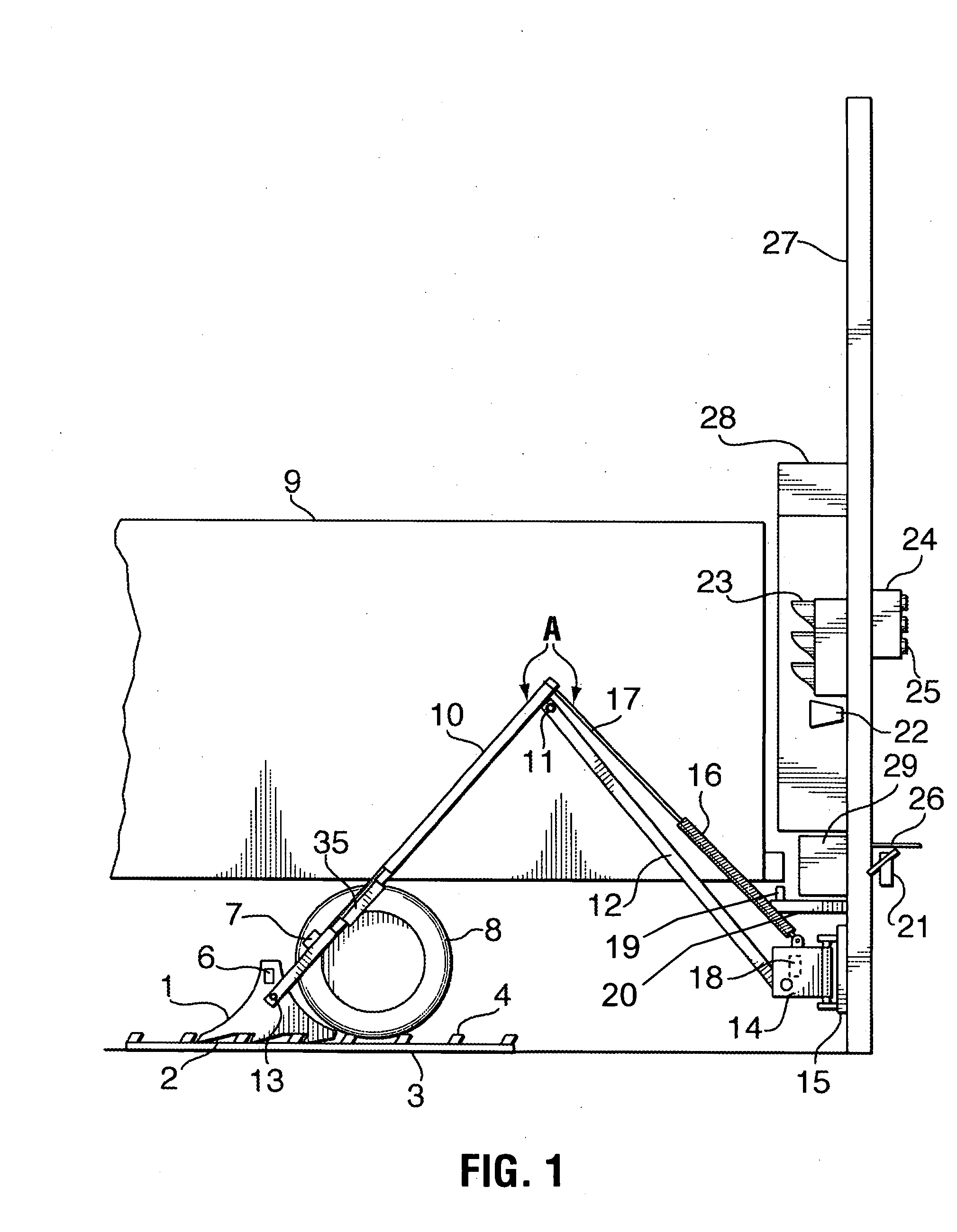
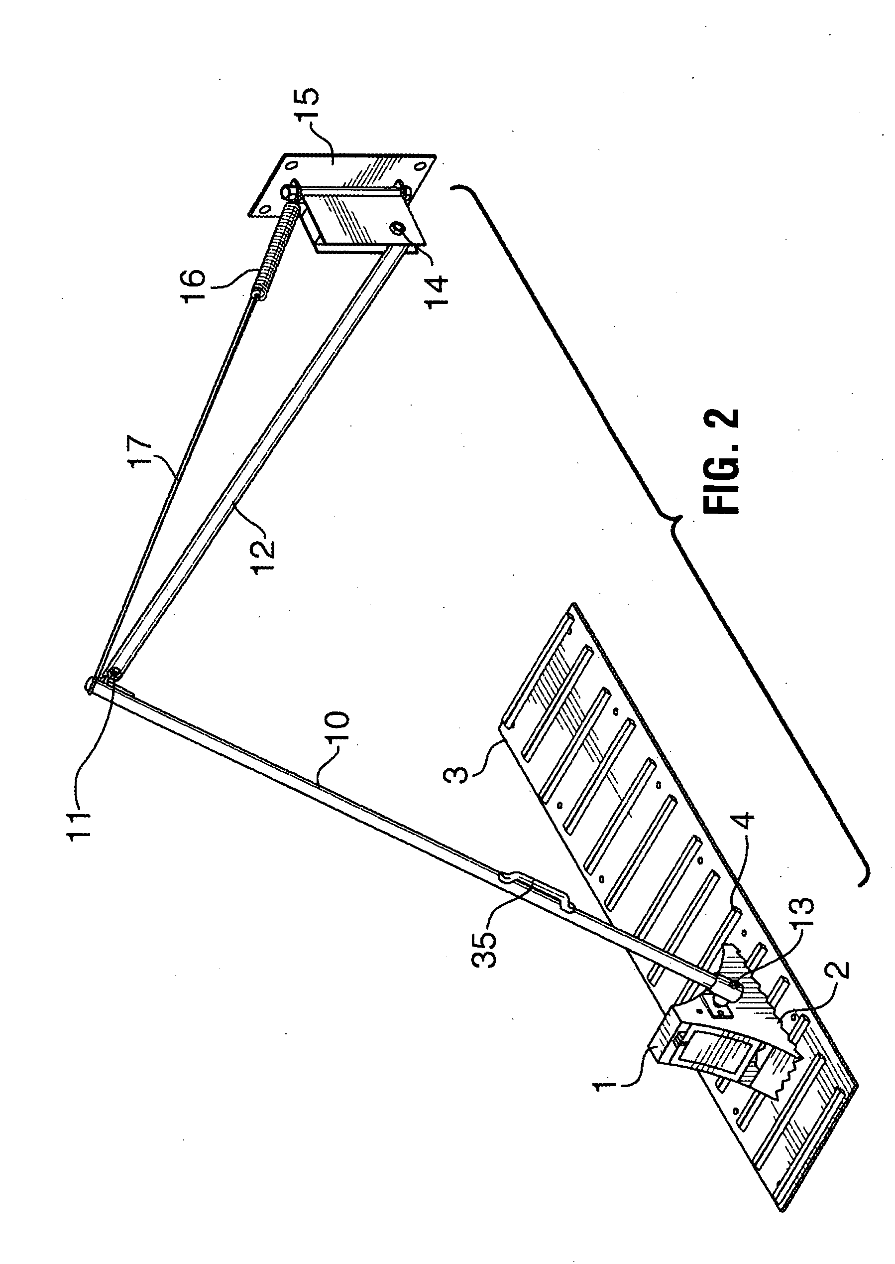
[0022] Referring to drawings, FIGS. 1 and 2 show the present invention comprising a wheel chock 1 attached to a wheel chock support means including a movable arm A consisting of a front arm 10 pivotally attached to a rear arm 12. Rear arm 12 is pivotally attached to a loading dock 27 by means of a pivot or bracket 14. A tension means such as an extension spring 16 is attached by one end to a pivot 14 and by another end to an upper portion of the front arm 10 by means of a cable or steel rod 17. Pivot 14 allows the arm A to be rotated left and right and up and down, and to move it into storage position, in close proximity to the dock face (not shown) when not in use.

[0023] A supporting element 3 is fixed on the ground in the vicinity of the loading dock and comprises an elongated plate long enough to spread at least under one axle of a truck 9 during loading operation to facilitate a proper engagement of a wheel chock 1 with the plate 3. A base portion of the chock 1 is provided with...

second embodiment

[0033]FIG. 3 shows the present invention wherein instead of one spring there are used two springs 16a and 16b. In this embodiment spring 16b is attached between the pivot 14 and the rear arm 12 by means of a protrusion 30. Second spring 16a is attached by one end to the pivot 14 and by another end to the upper portion of the front arm 10 by means of the cable 17. Second spring 16a is provided to pull the upper portion of the front arm 10 to facilitate easy handling of a big chock. The sensor 7 senses when wheel 8 engaging the chock 1 in the same manner as previous embodiment.

[0034] For both embodiments shown on FIG. 1 and FIG. 3 the attachment point of cable or rod 17 depends upon the length of the front arm 10, weight of said arm 10 and chock 10 and the strength of the tension means.

[0035]FIGS. 4 a, b and c show different modifications of the configuration of the base portion of the chock 1 and stoppers 4 of the supporting plate 3. FIG. 4a shows base portion of the chock provided ...

third embodiment

[0048]FIG. 8 shows the present invention comprising the chock 1 and supporting plate 3 similar to the one shown on FIG. 1. In this embodiment, wheel chock support means comprise a handle 61 and set of wheels 62 mounted on a side of the chock 1. Chock 1 is moved to the proper position manually by the driver using handle 61 and wheels 62. There are also a set of skis 63 attached beside wheels 62 which may be used during winter season.

[0049] The present invention has the following advantages over all known systems: [0050] it is simple and easy to operate due to non-jamming mechanism of the arm; [0051] involves the driver in the safety process; [0052] interlocks with dock leveller; [0053] arm can be extended up to 14 feet from the loading dock; [0054] minimum maintenance is required; [0055] galvanized assembly provides excellent durability; [0056] non ICC bar dependent; [0057] easy snow removal when the arm is stored; [0058] presence of highly visible warning system when truck departs p...


PUM


Abstract

Wheel chock restraint system comprising a wheel chock, a supporting element mounted on the ground in vicinity of a loading dock and a wheel chock support assembly connected by one end to the wheel chock and by another end in vicinity of the loading dock. A base portion of the chock is provided with first engagement elements and the supporting elements are provide with corresponding second engagement elements. The first engagement elements are adapted to cooperate with the second engagement elements, thus creating a retention force directed away from the loading dock and preventing the chock from sliding away from the wheel of a vehicle making an attempt to depart prematurely from the loading dock. Wheel chock support assembly is adapted to ensure a secure positioning of the chock under the wheel of the vehicle during loading and unloading operation by creating an engagement force directed towards the loading dock and pressing the chock against the wheel. The first engagement elements comprise a plurality of teeth extending downwardly from the base portion of the chock under a predetermined angle and the second engagement elements are a plurality of stoppers extending upwardly from the supporting element. This system also comprises an anti-theft locking means, wherein these locking means together with the first and second engagement means are adapted to securely lock the chock on the wheel of the vehicle and to prevent any unauthorized removal of the chock and theft of the vehicle.

Description

[0001] This is a divisional application of the previously filed application Ser. No. 10 / 370,771 filed on Feb. 24, 2003.[0002] The present invention relates to wheel chocks, and more particularly to a wheel chock restraint system provided to engage the wheel of a truck to prevent it from moving away from the loading dock during loading and unloading. [0003] Loading and unloading operations are hazardous for fork lifts entering and exiting the truck trailer. It is imperative that a truck remain immovably docked to the loading dock to prevent moving fork lifts from falling through the space created if a truck trailer moves truck away from the loading dock during loading and unloading. [0004] There are known two main kinds of restraint systems: ICC bar restraint systems to prevent the truck from moving away from the dock, and wheel restraint systems. However, while the first system is suitable for a majority of trailers, there are several configurations of trucks that cannot be secured ...

Claims


Application Information

Patent Timeline
Patent Type & Authority Applications(United States)
IPC IPC(8): B60T1/14B60T3/00B65G67/02B65G69/00
CPCB60T3/00B65G69/005
Inventor JETTE, GAETAN
Owner 9172 9863 QUEBEC
Why Eureka
Try Eureka