Precision frequency and phase synthesis with fewer voltage-controlled oscillator stages

a phase synthesis and frequency technology, applied in the field of integrated circuits, can solve the problems of significant noise source in these circuits, scaling limited by the performance of control circuits, and the increase of the number of synthesis paths arbitrarily, so as to reduce the frequency error

Active Publication Date: 2006-07-06
TEXAS INSTR INC
View PDF1 Cites 11 Cited by
  • Summary
  • Abstract
  • Description
  • Claims
  • Application Information

AI Technical Summary

Benefits of technology

[0012] It is therefore an object of this invention to provide a frequency synthesis circuit based on the flying-adder architecture in which frequency error is reduced without affecting the resolution of the circuit.

Problems solved by technology

In this way, the number of synthesis paths can be increased arbitrarily, with the scaling limited by the performance of control circuits for the output multiplexer.
However, it has been observed, in connection with this invention, that the most significant source of noise in these circuits is design and layout mismatch among the multiple VCO stages.
This noise directly causes frequency error in the output clock signal.
However, simply reducing the number of VCO stages would correspondingly reduce the number of available phases applied to the flying-adder synthesizer, and thus reduce the resolution at which the frequency of the output clock signal may be selected.
As such, the ability to improve the accuracy of the flying-adder frequency synthesis architecture in this way has not yet been available.

Method used


Image

  • Precision frequency and phase synthesis with fewer voltage-controlled oscillator stages
  • Precision frequency and phase synthesis with fewer voltage-controlled oscillator stages
  • Precision frequency and phase synthesis with fewer voltage-controlled oscillator stages

Examples


Embodiment Construction

[0025] The present invention will be described in connection with its preferred embodiment, namely as implemented into a clock generator circuit such as may be used in many various system applications. Examples of such system applications include video decoders, communications systems such as modems and transceivers, and the like. Accordingly, it is to be understood that the following description is provided by way of example only, and is not intended to limit the true scope of this invention as claimed.

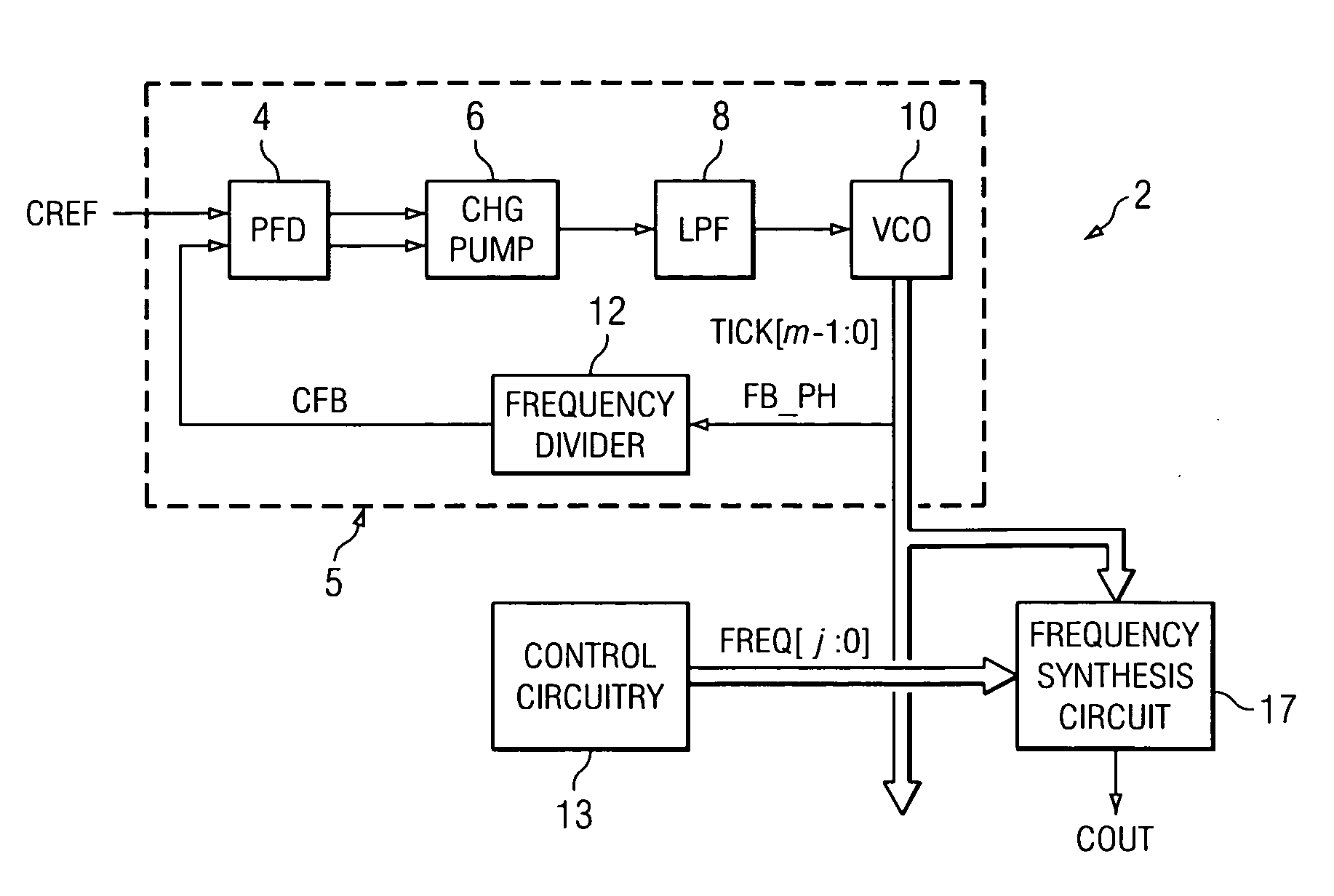
[0026] Referring first to FIG. 1, the construction of clock generation circuit 2 according to a preferred embodiment of the present invention will now be described in general. Clock generation circuit 2 is a phase-locked loop (PLL) based clock circuit, and as such includes PLL 5 which generates multiple phases of a clock signal, phase-locked to a reference clock received on line CREF. Phase-frequency detector (PFD) 4 that compares the relative phases of this reference clock on line ...


PUM


Abstract

A clock synthesis circuit) including a phase-locked loop and one or more frequency synthesis circuits is disclosed. The phase-locked loop includes a voltage-controlled oscillator (VCO) having a sequence differential stages o produce equally spaced clock phases. The frequency synthesis circuit includes a sequence of adder-and-register units that select one of the VCO clock phases. An output multiplexer receives each of the selected clock phases, and selects among these clock phases in sequence; the output of the multiplexer is applied to a first toggle flip-flop that changes state in response to rising edge transitions at the output of the multiplexer. A second toggle flip-flop is clocked by the output of the first toggle flip-flop, itself toggling in response to rising edge transitions at the output of the first toggle flip-flop. One or more additional flip-flops can be similarly connected in sequence. The additional toggle flip-flop enables the VCO to be formed with fewer stages for a given frequency resolution, reducing noise and thus frequency error.

Description

CROSS-REFERENCE TO RELATED APPLICATIONS [0001] This application claims priority, under 35 U.S.C. §119(e), of Provisional Application No. 60 / 641,314, filed Jan. 3, 2005.STATEMENT REGARDING FEDERALLY SPONSORED RESEARCH OR DEVELOPMENT [0002] Not applicable. BACKGROUND OF THE INVENTION [0003] This invention is in the field of integrated circuits, and is more specifically directed to clock generation circuits. [0004] As is fundamental in the art, many modern electronic systems include numerous integrated circuits that operate in conjunction with one another. For example, consumer-oriented systems such as televisions and home theaters include video decoders for decoding an input video signal into digital video output signals that are synchronized with a synchronization pulse contained within the incoming video signal itself. Modern spread-spectrum communications transmitters and receivers require the generation of high-frequency clock signals for the modulation and demodulation, respectiv...

Claims


Application Information

Patent Timeline
Patent Type & Authority Applications(United States)
IPC IPC(8): H03B27/00
CPCH03L7/0995H03L7/18
Inventor XIU, LIMINGYOU, ZHIHONG
Owner TEXAS INSTR INC
Why Eureka
Try Eureka