Light measuring apparatus and method for measuring monochromatic light

Active Publication Date: 2006-07-06
KONICA MINOLTA SENSING INC
View PDF4 Cites 19 Cited by
  • Summary
  • Abstract
  • Description
  • Claims
  • Application Information

AI Technical Summary

Benefits of technology

[0017] Accordingly, color luminance values and the like can be measured with high precision by maxim

Problems solved by technology

However, there is a disadvantage of being difficult to meet a required approximation precision due to the restriction of usable filters and variations in the characteristics of the usable filters.
However, a bright optical system having a high resolving power is necessary in order to obtain spectral data as above, thereby presenting a problem of necessitating the use of a light measurin

Method used


Image

  • Light measuring apparatus and method for measuring monochromatic light
  • Light measuring apparatus and method for measuring monochromatic light
  • Light measuring apparatus and method for measuring monochromatic light

Examples


Example

[0097] Several specific examples according to the embodiment and comparative examples to be compared with the specific examples are shown concerning the half power band width A and the center wavelength interval B of the light receiving sensors of the above light receiving sensor array 43. In the examples (comparative examples), the approximation precision of the composite spectral responsitivities to the CIE color matching function z(λ) and S / N ratios based on the weighting coefficients for the respective wavelengths were evaluated when the center wavelength interval (wavelength pitch) of the light receiving sensors was set at 10 nm and the half power band width A was set at 10 nm, 15 nm, 20 nm, 30 nm, 40 nm and 50 nm.

[0098] FIGS. 15 to 18 are graphs showing data according to the examples of the embodiment, whereas FIGS. 19 and 20 are graphs showing data according to the comparative examples. FIGS. 15A to 20A are graphs showing a spectral responsitivity of one light receiving sens...

Example

[0104] Although the approximation precision is relatively good in the comparative example 2 where the ratio of the half power band width A to the center wavelength interval B is set at 5, some of the weighting coefficients take negative values as is clear from FIG. 20C. Further, different from the example 4, a rate of the weighting coefficients taking negative values to all the weighting coefficients increases to about 38%, whereby the deterioration of the S / N ratio is conspicuous.

[0105] The above S / N ratio is additionally described. First, when the ratio of the half power band width A to the center wavelength interval B increases, curves of the spectral responsitivities of the respective light receiving sensors become wider than the curve of the color matching function z(λ), with the result that it is necessary to narrow the curve of the composite spectral responsitivity by letting the weighting coefficients of some of the light receiving sensors take negative values in order to a...


PUM


Abstract

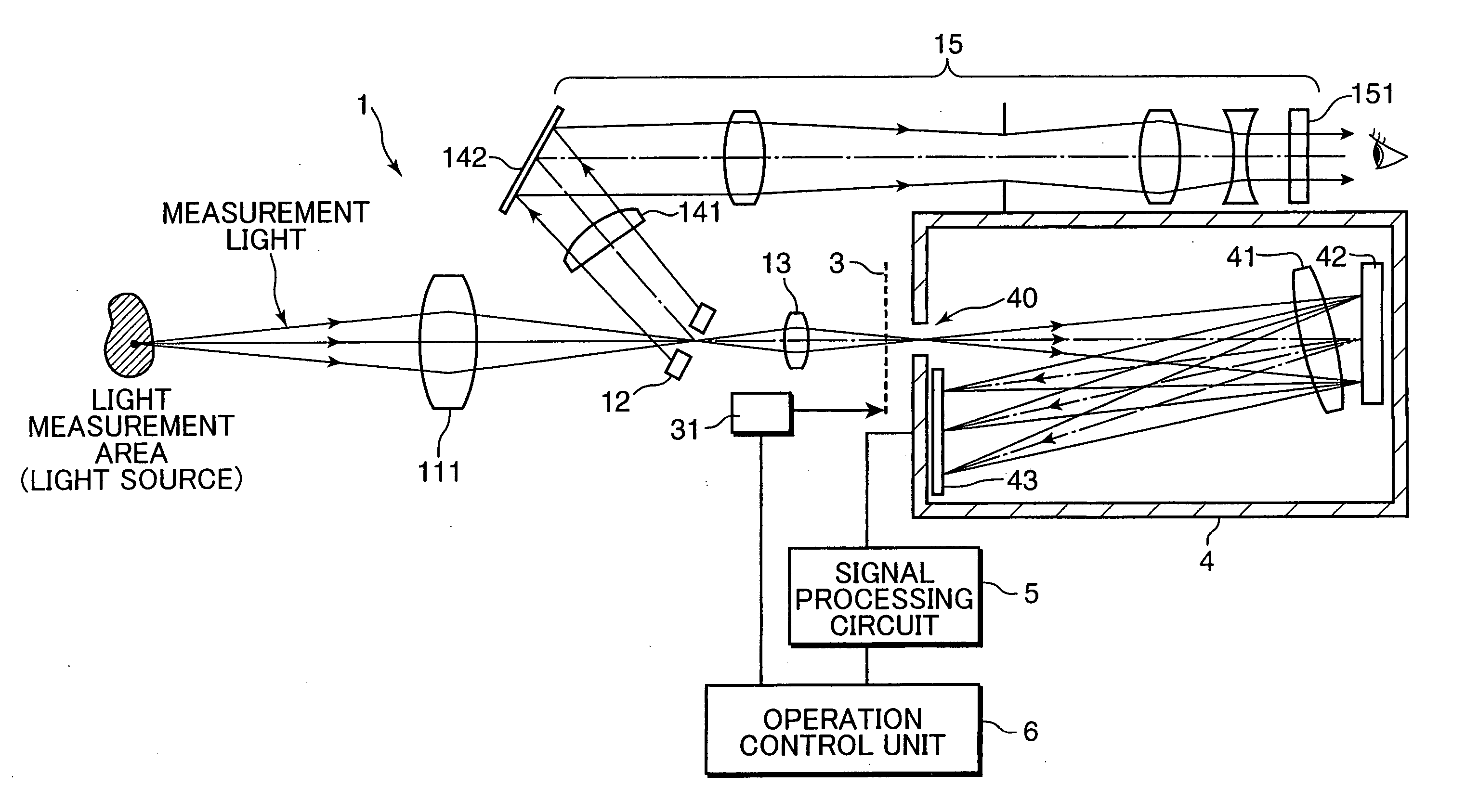
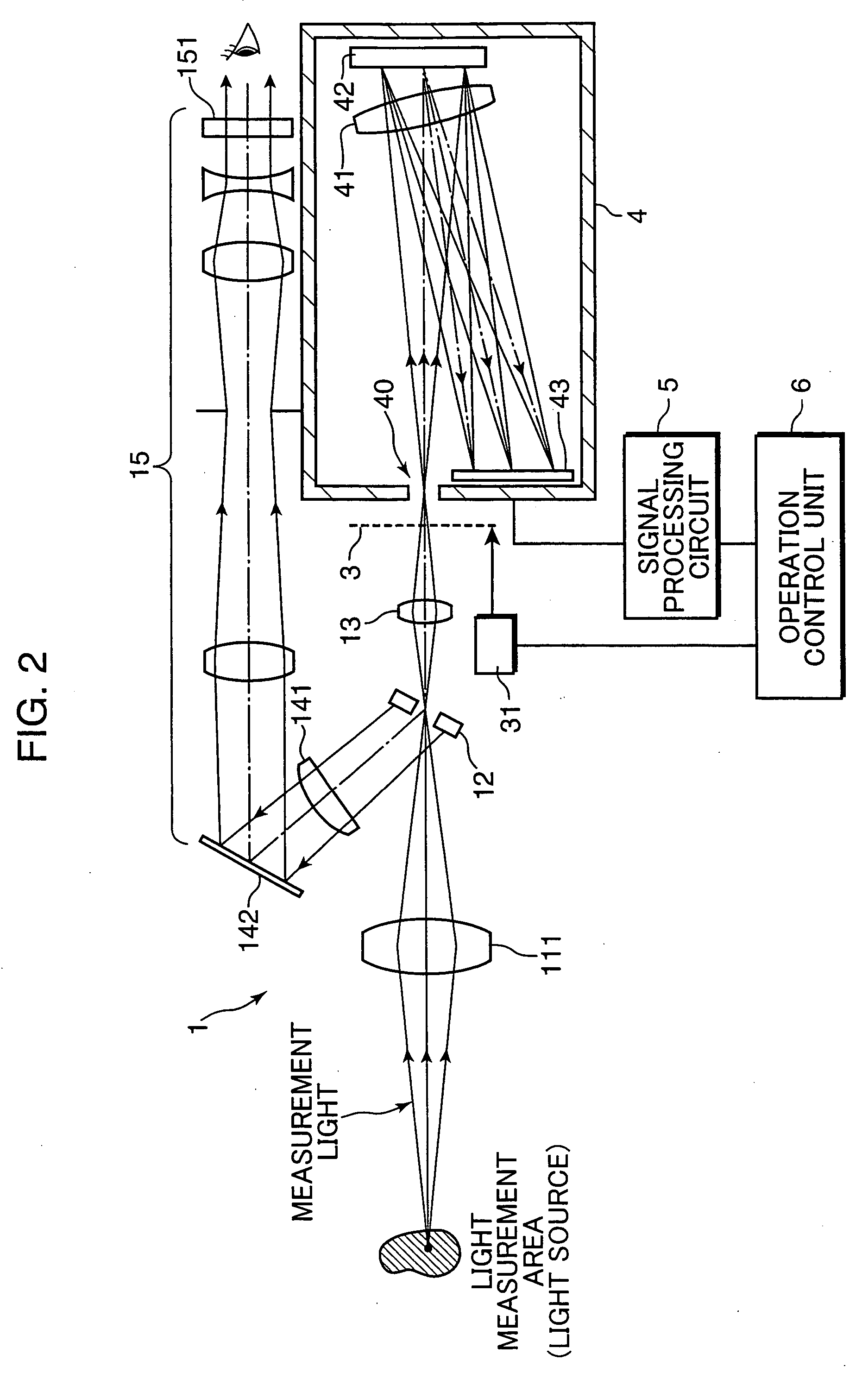
A color luminance meter 1 is provided with a polychrometer 4 as a spectral optical system including a light receiving sensor array 43, a signal processing circuit 5 and an operation control unit 6. The operation control unit 6 carries out calculations to obtain characteristics of a measurement light based on a specified spectral responsitivity, using light reception signals and specified weighting coefficients. The spectral responsitivities of light receiving sensors constructing the light receiving sensor array 43 are selected such that B≧5 nm and A/B lies within a range of 1.5 to 4.0 when A, B denote the half power band width of the spectral responsitivities and a center wavelength interval of the spectral responsitivities. Accordingly, there can be provided a light measuring apparatus capable of maximally suppressing errors to highly precisely measure color luminance values and the like even in a measurement of a light lying in a narrow band such as a monochromatic light.

Description

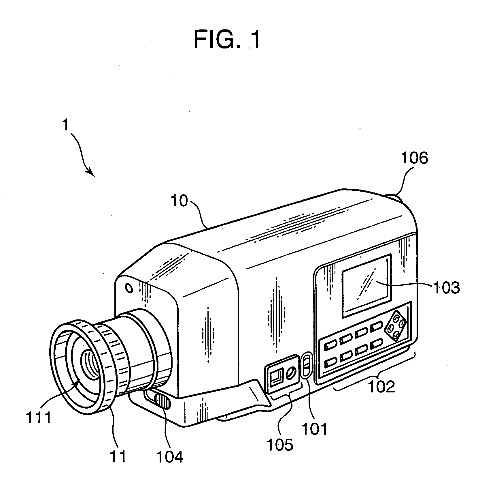
This application is based on patent application No. 2005-000583 filed in Japan, the contents of which are hereby incorporated by references. BACKGROUND OF THE INVENTION [0001] The present invention relates to a light measuring apparatus for obtaining characteristics of light from a light source or light to be measured such as light reflected by or transmitted through an illuminated sample and particularly to a spectral color meter for measuring color luminance values and the like of visible light (monochromatic light) and a method for measuring monochromatic light. [0002] A color meter, one mode of a light measuring apparatus, for measuring color values of an incident light needs to have spectral responsitivities approximate to color matching functions of a standard observer recommended by the CIE (International Commission on Illumination). In recent years, with an increase of light sources for emitting a monochromatic light or a combination of monochromatic lights such as liquid cr...

Claims


Application Information

Patent Timeline
IPC IPC(8): G01J3/28
CPCG01J3/02G01J3/0232G01J3/0248G01J3/027G01J3/0272G01J3/2803G01J3/46G01J3/465G01J3/502G01J2003/467
Inventor NAGASHIMA, YOSHIYUKIIMURA, KENJISHIMIZU, SHINJITSURUTANI, KATSUTOSHI
Owner KONICA MINOLTA SENSING INC
Why Eureka
Try Eureka