Leakage current detection and interruption circuit

Inactive Publication Date: 2006-07-06
TECH RES
View PDF71 Cites 37 Cited by
  • Summary
  • Abstract
  • Description
  • Claims
  • Application Information

AI Technical Summary

Benefits of technology

[0038] In one example of the invention, the disconnect switch includes a solenoid operated switch. Preferably, the disconnect switch includes a normally closed solenoid operated switch and a latch for maintaining the disconnect switch in an open condition upon

Problems solved by technology

As a result a relay connected to the collector of the transistor is triggered, changing the state of its contacts and causing disconnection of the protected motor.
In case closing of the primary test switch contacts fails to trip the GFCI, subsequent closing of the secondary test switch conta

Method used


Image

  • Leakage current detection and interruption circuit
  • Leakage current detection and interruption circuit
  • Leakage current detection and interruption circuit

Examples


first embodiment

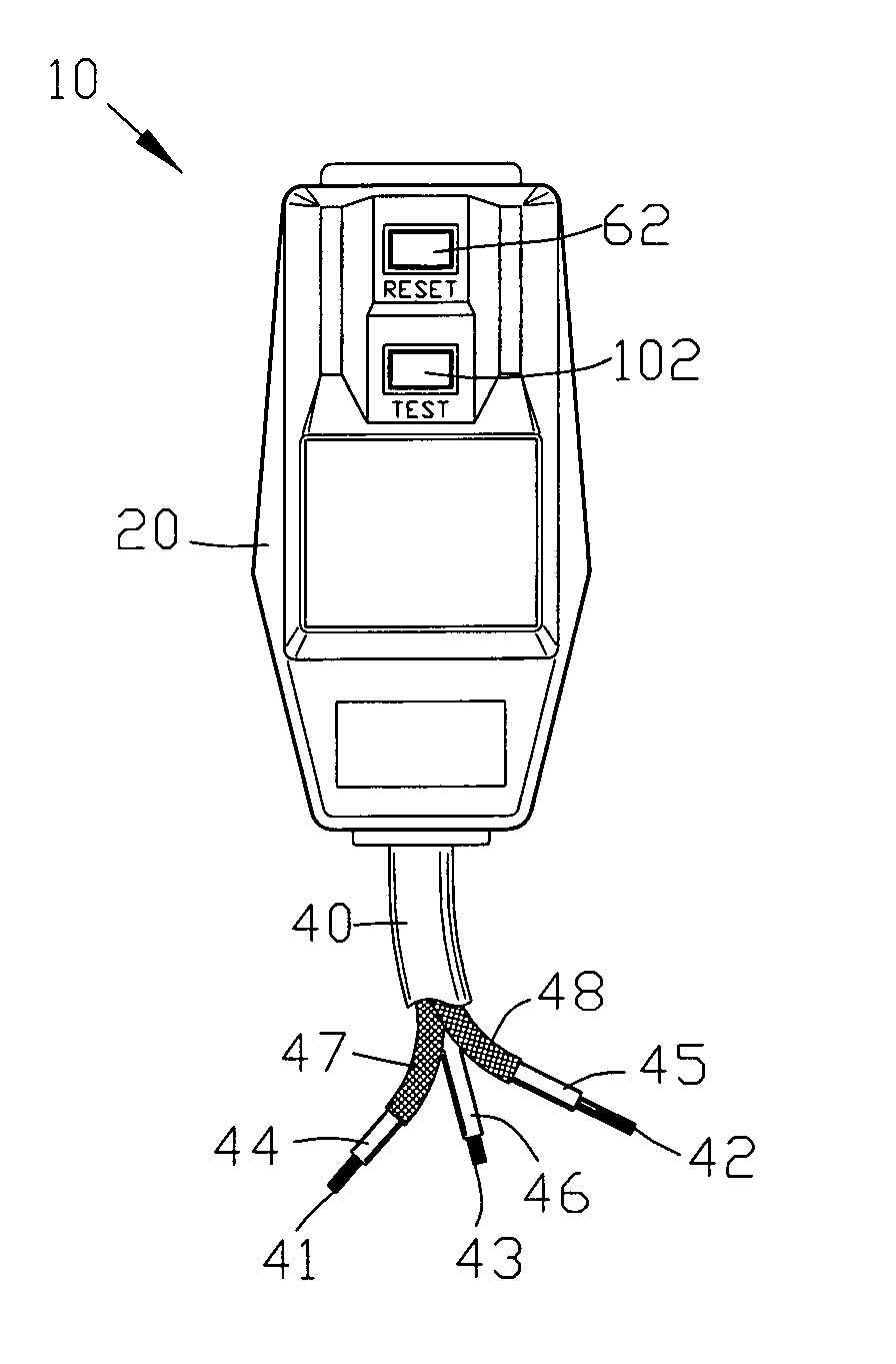
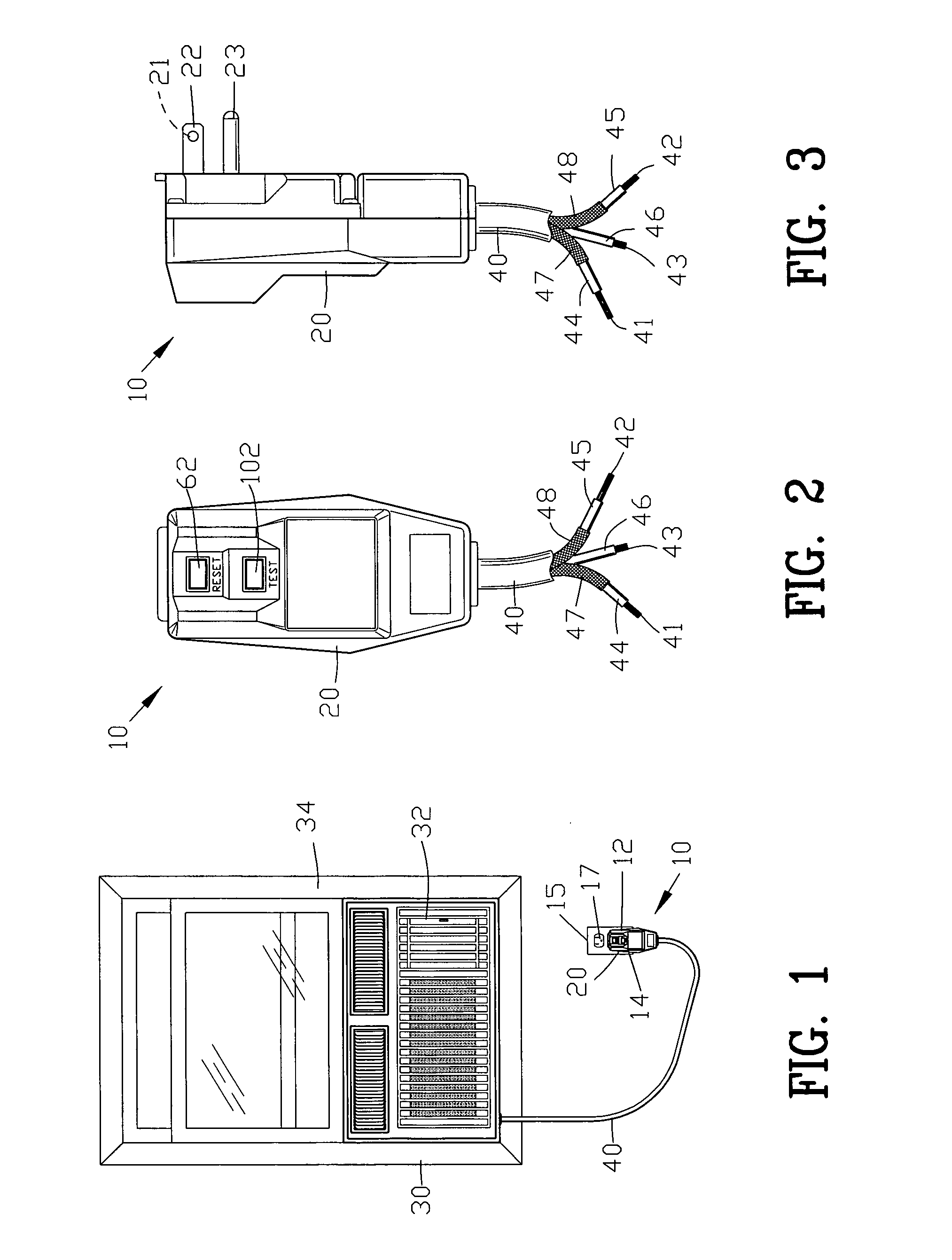
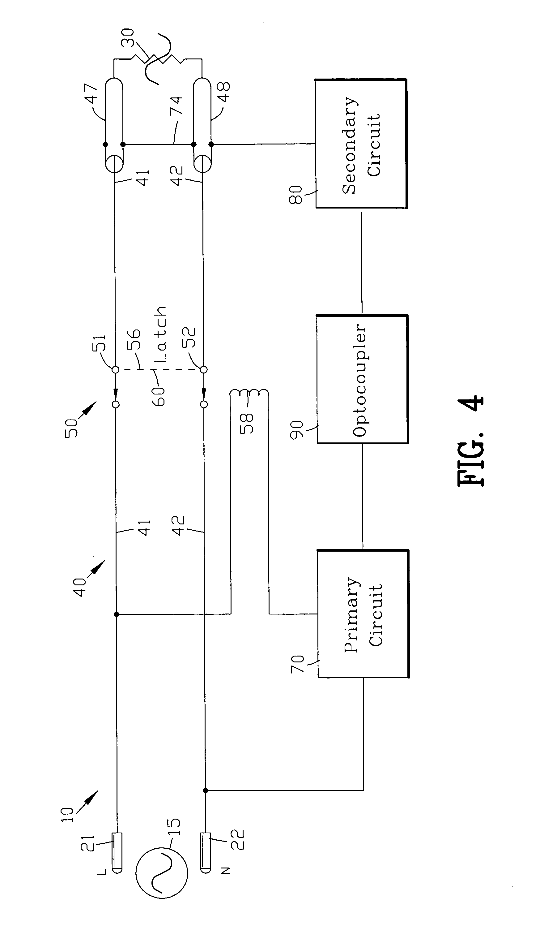
[0091]FIG. 12 is a circuit diagram of the circuit 10 of FIG. 4. The first and second terminals 21 and 22 extending from the housing 20 are connected to the wires 41 and 42 of the wire assembly 40. A surge suppressor shown as a metal oxide varistor 26 is connected across the first and second wires 41 and 42. The function and operation of the metal oxide varistor 26 should be well known to those skilled in the art.

[0092] The disconnect 50 is interposed within the wire assembly 40 with the first and second switches 51 and 52 located within the first and second wires 41 and 42. The disconnect switch 50 is shown in the closed or reset condition.

[0093] The primary circuit 70 is located on a primary side of the disconnect switch 50 for controlling the disconnect switch 50. The primary circuit 70 opens the disconnect switch 50 upon the secondary circuit 80 sensing a leakage current from one of the wire 41 and 42. The disconnect switch 50 is controlled through the solenoid coil 58 by the pr...

second embodiment

[0107]FIG. 17 is a circuit diagram of the circuit 110 of FIGS. 1-4. Similar parts are labeled with similar reference numerals raised by the number 100. In this example, the electrical power source 115 is shown as a conventional 220 volt alternating current (AC) power source. Although the electrical power source 115 has been shown as conventional 220 volt alternating current (AC) power source, it should be appreciated by those skilled in the art that the present invention may be adapted to virtually any type of power source.

[0108] In this example, a voltage dropping resistor 167 is inserted in series between the first wire 141 and diode 168. In this example, the voltage divider network 171 is formed from resistor 172 and zener diode 173. The combination of the voltage dropping resistor 167 and the voltage divider network 171 comprising resistor 172 and zener diode 173 provides a minor conventional current through solenoid coil 158 to supply a collector voltage for the phototransistor...

third embodiment

[0109]FIG. 18 is a circuit diagram of the circuit 210 of FIGS. 1-4. In this embodiment of the invention the disconnect switch 250 is interposed between the source 215 and the load 230. The primary circuit 270 received operating power from a primary side or source side of the disconnect switch 250 by conductors 271 and 272. The secondary circuit 280 received operating power from a secondary side or load side of the disconnect switch 250 by conductors 281 and 282. The secondary circuit 280 is optically connected to the primary circuit 270 by the optocoupler 290.

[0110] In this example a conductor 292 connects a sensor 294 to the secondary circuit 280. The sensor 294 senses any leakage from either the first or the second wires 241 and 242. The sensor 294 may be the ground wire normally included in a conventional 110 volt alternating current power cord.

[0111] When the sensor 294 senses a leakage from either the first or the second wires 241 and 242, the secondary circuit 280 optically a...


PUM


Abstract

A circuit is disclosed for disconnecting a power source upon the detection of a leakage. The circuit comprises a disconnect switch for disconnecting the power source. A primary circuit controls the disconnect switch. A secondary circuit senses a leakage current. An optical switch interconnects the primary circuit and the secondary circuit for opening the disconnect switch upon the secondary circuit sensing a leakage current. The circuit is suitable for use as a leakage current detection and interruption circuit for completely electrically disconnecting and isolating the power source and the primary circuit from the secondary circuit.

Description

BACKGROUND OF THE INVENTION [0001] 1. Field of the Invention [0002] This invention relates to electrical power circuit and more particularly to a circuit for disconnecting a power source upon the detection of a leakage current. [0003] 2. Background of the Invention [0004] Various types of electrical protective devices have been proposed by the prior art for reducing the possibility of dangerous electrical shocks as well as the possibility of electrical fires. One general class of prior art electrical protective devices is a commonly referred to as a ground fault circuit interrupter (GFCI). A ground fault circuit interrupter disconnects a power source upon the detection of an undesired grounding of a power line, such as by a person inadvertently being connected between the power line and a ground. Other types of types of electrical protective devices include appliance leakage current interrupters (ALCIs), equipment leakage current interrupters (ELCIs) and immersion detection circuit ...

Claims


Application Information

Patent Timeline
IPC IPC(8): H02H3/00
CPCH01H73/44H01H83/02H02H1/0038H02H1/0069H02H3/044H02H3/16H02H3/33H02H5/10H02H3/32
Inventor WILLIAMS, THOMAS S.
Owner TECH RES
Why Eureka
Try Eureka