Cooling apparatus, system, and associated method

a technology of cooling apparatus and cooling system, applied in the direction of cooling/ventilation/heating modification, circuit fluid transportation, circuit thermal arrangement, etc., can solve the problems of large temperature gradient, adversely affecting the performance of electronic devices, large temperature gradient, etc., and achieve the effect of transferring heat efficiently and effectively from the printed circuit board

Active Publication Date: 2006-07-06
THE BOEING CO
View PDF22 Cites 77 Cited by
  • Summary
  • Abstract
  • Description
  • Claims
  • Application Information

AI Technical Summary

Benefits of technology

[0009] The invention addresses the above needs and achieves other advantages by providing an improved cooling system that is capable of employing a pulsating heat pipe for cooling a printed circuit board. For example, the pulsating heat pipe may be positioned within a chassis housing in close proximity to the printed circuit board. Thus, the pulsating heat pipe may be positioned along, or adjacent to, one or more printed circuit boards such that the cooling system may readily and effectively transfer heat away from the printed circuit boards. In one embodiment, the cooling system may utilize a loop heat pipe in conjunction with the pulsating heat pipe to provide intermediate cooling between the pulsating heat pipe and a heat sink.
[0018] The present invention therefore provides a cooling system capable of cooling PCB's installed within a chassis housing. The cooling system is adaptable to a variety of technologies, including avionics, and may be customized for various cooling needs. The cooling system of one advantageous embodiment employs a PHP that takes up a minimal amount of space by positioning the evaporator between pairs of PCB's, and positioning the condenser within the wall of the chassis housing. In addition, PHP's are generally known to have a lower manufacturing cost, have a simple and lightweight internal structure, and have a higher heat transfer capability than conventional avionics cooling techniques. Thus, the cooling system is capable of reducing the temperature gradient between the heat sources and the heat sink, as well as reducing the thermal resistance between the PCB's and PHP. Because of the improved heat transfer characteristics, the cooling system is better capable of handling the increasing demands of new electronic devices in avionics and other technologies.

Problems solved by technology

Because of high thermal resistance in the heat transfer path, the waste heat load generally increases with further operation, which in turn, leads to a larger temperature gradient (ΔT) between the electronic devices that are generating heat and the heat sink.
This larger ΔT may adversely affect the performance of the electronic devices.
At steady state, heat transfer is achieved by continuous oscillatory movements from the evaporating region to the condensing region, which is caused by instant pressure imbalance among different turns.
The increasing heat dissipation requirements therefore cause a very large temperature gradient when traditional cooling solutions are utilized.

Method used


Image

  • Cooling apparatus, system, and associated method
  • Cooling apparatus, system, and associated method
  • Cooling apparatus, system, and associated method

Examples


Embodiment Construction

[0031] The present invention now will be described more fully hereinafter with reference to the accompanying drawings, in which some, but not all embodiments of the invention are shown. Indeed, this invention may be embodied in many different forms and should not be construed as limited to the embodiments set forth herein; rather, these embodiments are provided so that this disclosure will satisfy applicable legal requirements. Like numbers refer to like elements throughout.

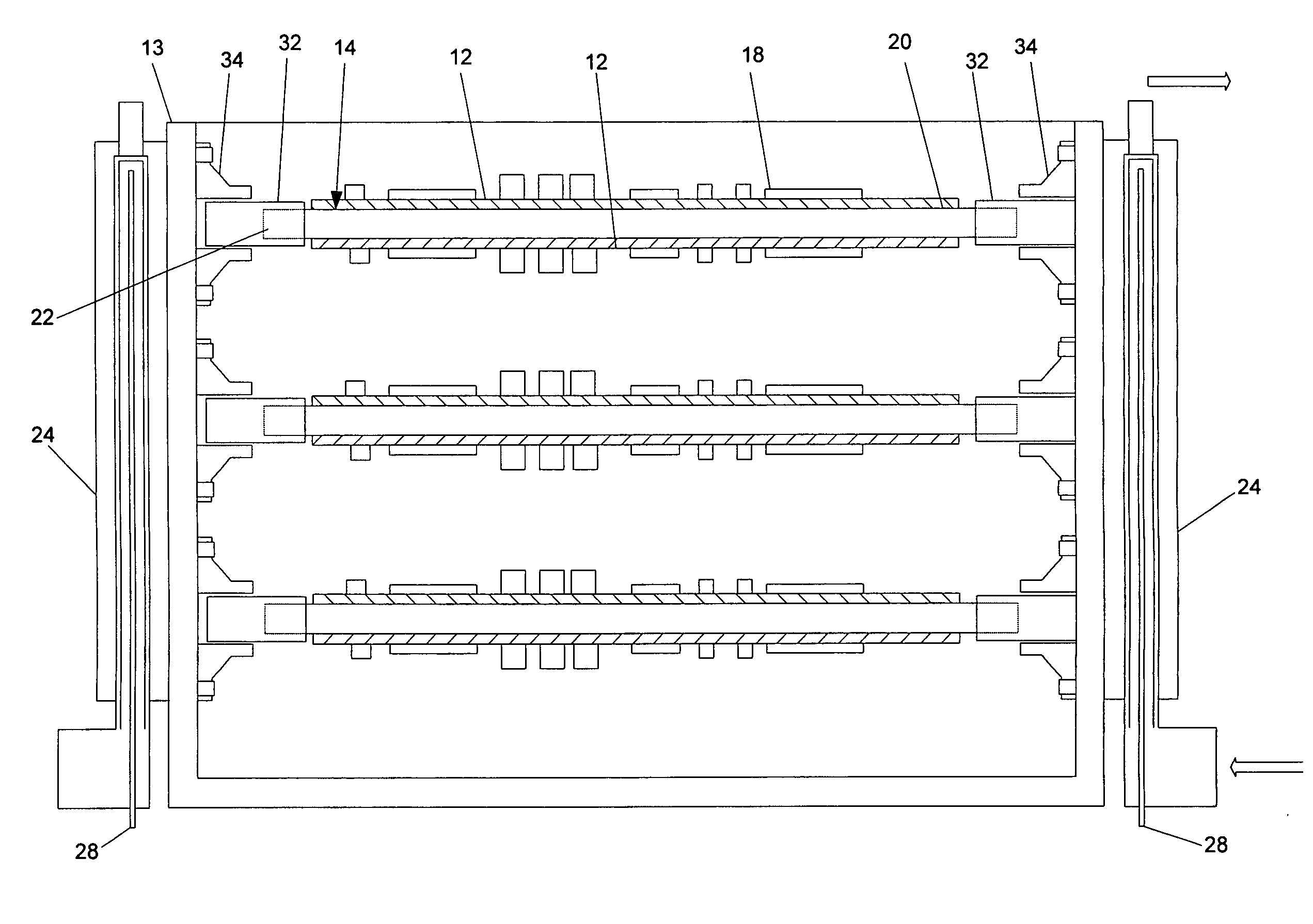
[0032] Referring now to the drawings and, in particular to FIG. 3 there is shown a cooling system 10, according to one embodiment of the present invention. The cooling system 10 generally includes a plurality of printed circuit boards 12 (“PCB's”) installed within a chassis box 13. A portion of a pulsating heat pipe 14 (“PHP”) is positioned adjacent a respective PCB and, more typically, between a pair of PCB's 12 within the chassis box 13. The remaining portion of the PHP 14 is positioned adjacent to or within a...


PUM


Abstract

A cooling apparatus, system, and method are provided. The cooling apparatus includes at least one printed circuit board having opposed major surfaces, and at least one electrical component or other heat source positioned on one major surface of the printed circuit board. The cooling apparatus also includes a pulsating heat pipe having at least a portion that is positioned to either extend along and proximate to one of the major surfaces or be embedded within the printed circuit board. As such, the pulsating heat pipe is capable of transferring heat from the printed circuit board.

Description

BACKGROUND OF THE INVENTION [0001] 1) Field of the Invention [0002] The present invention relates to a cooling system and, more particularly, to a cooling system employing a pulsating heat pipe for cooling a printed circuit board. [0003] 2) Description of Related Art [0004] In avionics and other applications, printed circuit boards (“PCB's”) are commonly mounted within a metallic chassis box. The heat generated by electronic devices carried by the PCB is dissipated by transfer to a metal (aluminum) wall of the chassis box through the PCB's. The heat is then sent to an external heat sink by conduction through the metal chassis wall, and is finally taken away by either cool air circulating about the heat sink or a cold plate. Because of high thermal resistance in the heat transfer path, the waste heat load generally increases with further operation, which in turn, leads to a larger temperature gradient (ΔT) between the electronic devices that are generating heat and the heat sink. Thi...

Claims


Application Information

Patent Timeline
Patent Type & Authority Applications(United States)
IPC IPC(8): H05K7/20
CPCH05K7/20672H05K7/20681H05K1/0203H05K1/0272F28D15/0266
Inventor ASFIA, JULIE F.CHEN, CHUNG-LUNGCAI, QINGJUN
Owner THE BOEING CO
Why Eureka
Try Eureka