Guide blade of axial-flow fan shroud

a technology of axial flow and guide blades, which is applied in the direction of machines/engines, stators, liquid fuel engines, etc., can solve the problems of disadvantageous degrading and achieve the effect of improving the performance of air conditioning systems and enhancing the blowing efficiency in the axial direction

Active Publication Date: 2006-07-06
HANON SYST
View PDF8 Cites 44 Cited by
  • Summary
  • Abstract
  • Description
  • Claims
  • Application Information

AI Technical Summary

Benefits of technology

[0020] The present invention has been devised to solve the foregoing problems occurring in the prior art, and it is therefore an object of the present invention to provide a guide blade of an axial flow fan shroud which converts both of rotational and radial velocity components of the air blown by an axial fan into an axial direction to spread in radial and rotational directions to enhance the blowing efficiency in the axial direction as well as to prevent high temperature heat generated by an engine room from flowing backward to a heat exchanger such as a condenser thereby improving the performance of an air conditioning system.

Problems solved by technology

However, since the angle of projection of the guide blade is 0° with respect to the axial line, the air passing through the axial flow fan is guided toward the engine in the rear in the axial direction of the fan colliding into the engine so that high temperature heat generated by the engine flows backward toward the heat exchanger such as a condenser to elevate the refrigerant pressure of the heat exchanger thereby disadvantageously degrading the performance of an air conditioning system.

Method used


Image

  • Guide blade of axial-flow fan shroud
  • Guide blade of axial-flow fan shroud
  • Guide blade of axial-flow fan shroud

Examples


Embodiment Construction

[0035] Hereinafter a preferred embodiment of the present invention will be described in detail with reference to the accompanying drawings.

[0036] The same or similar parts are designated with the same or similar reference numerals as in the prior art, and repeated description thereof will be omitted.

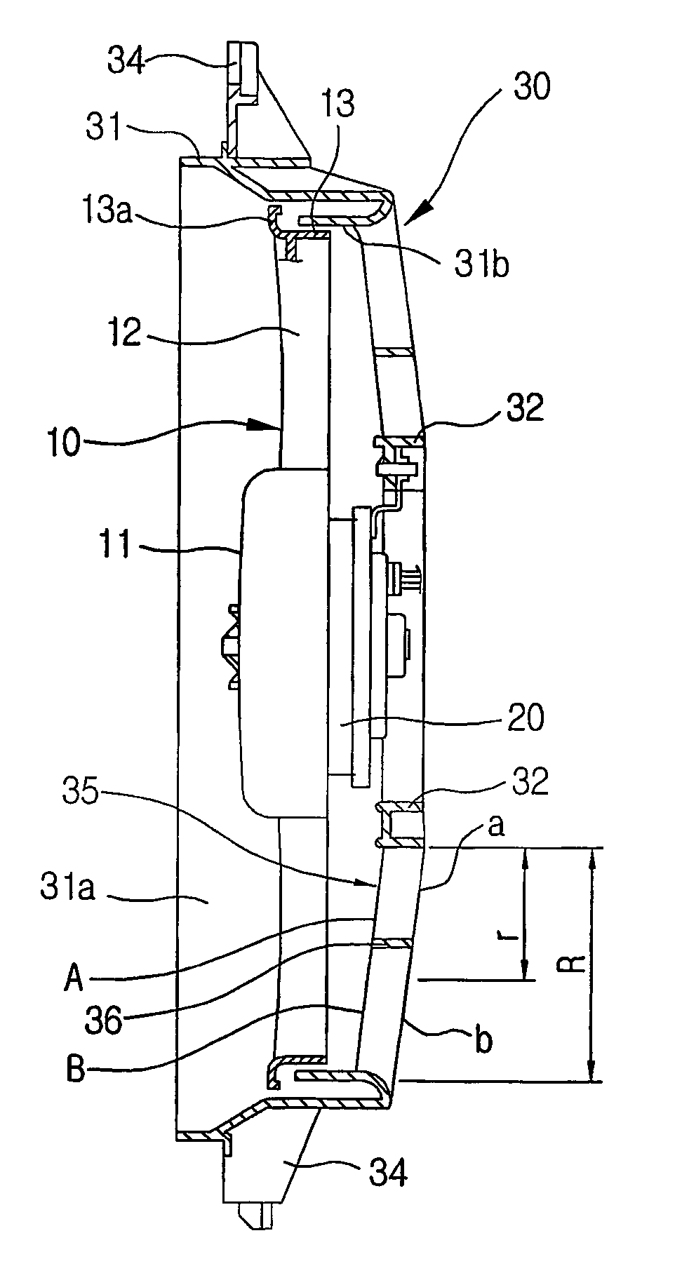
[0037]FIGS. 3 and 4 illustrate an axial flow fan shroud assembly of the present invention, in which an axial flow fan 10 and a shroud 30 are assembled into an integral unit.

[0038] The axial flow fan 10 includes an annular fan hub 11 and a number of blades 12 arrayed along the outer circumference of the fan hub 11 at a predetermined gap. The shroud 30 includes a motor support ring 32, guide blades 35 and a housing 31.

[0039] As shown in FIG. 4, the axial flow fan 10 is integrally provided with a fan band 13 which is coaxial with the fan hub 11. The fan band 13 fixedly connects the ends of the blades 12 to restrain vortex at the ends of the blades 12 thereby enhancing the blowing effici...


PUM


Abstract

The present invention discloses guide blades of an axial flow fan shroud for guiding the air blown by an axial flow fan in an axial direction, and more particularly, to a guide blade structure capable of preventing the backflow of high temperature heat from an engine room toward a condenser. A guide blade 35 of an axial flow fan shroud 30 comprises: a leading edge 37 for introducing the air blown by an axial flow fan 10 including a number of blades 12; a trailing edge 39 extended from the leading edge 37 to downstream; and an air flow guide surface 38 for guiding the blown air between the leading and trailing edges 37 and 39, wherein if a first outlet area a is defined by at a radius r from a root in the total length R of an angle of projection Aout of the guide blade 35 and a second outlet area b is defined by the remainder, the angle of projection Aout increases as approaching a tip with respect to an axial line in the second outlet area b.

Description

TECHNICAL FIELD [0001] The present invention relates to guide blades of an axial flow fan shroud for guiding the air blown by an axial flow fan in an axial direction, and more particularly, to a guide blade structure capable of preventing high temperature heat generated by an engine room from flowing backward to a condenser. BACKGROUND ART [0002] An axial flow fan is an apparatus for rotating a number of radially arrayed blades to blow the air in an axial direction, and includes a shroud which serves to guide the air blew in by the axial flow fan directly backward. [0003] The axial flow fan is used to ventilate a room or to feed the air into an air-cooled heat exchanger such as a radiator or condenser of an automobile in order to promote the heat dissipation thereof. [0004] In the meantime, the shroud includes a number of strip-shaped and fixed guide blades which are arrayed radially from the central axis of the axial flow fan in order to raise the blowing efficiency of the axial fl...

Claims


Application Information

Patent Timeline
Patent Type & Authority Applications(United States)
IPC IPC(8): F01D9/00F04D29/54F04D29/58
CPCF04D29/544F05D2250/52F04D29/54
Inventor CHO, KYUNGSEOKPARK, SEYOUNG
Owner HANON SYST
Why Eureka
Try Eureka