Sintered structures for vascular graft

a vascular graft and vascular artery technology, applied in the field of vascular artery artery artery artery artery artery artery artery artery artery artery artery artery artery artery artery artery artery artery artery artery artery artery artery artery artery artery artery artery artery artery artery artery artery artery artery artery artery artery artery artery artery artery artery artery artery

Inactive Publication Date: 2006-07-06
LIFESHIELD SCI
View PDF53 Cites 14 Cited by
  • Summary
  • Abstract
  • Description
  • Claims
  • Application Information

AI Technical Summary

Benefits of technology

[0010] The vascular graft of the present invention is for implantation within a body and has a PTFE tube structure including a length and inner and outer wall surfaces. The tube structure has a non-expanded portion formed from sintering a PTFE green tube extrudate and an expanded portion formed subsequent to the sintering. The expanded and non-expanded portions are of the same extrudate. The expanded portion has a region which adjoins the non-expanded portion wherein a degree of expansion of the region is limited by the non-expanded portion. The limiting of the expansion by the non-expanded portion is attenuated at a location of the region which is remote from the non-expanded portion. A method for making the vascular graft facilitates the formation of the non-expanded and expanded portions of the PTFE tube structure.

Problems solved by technology

For example, handling of the vascular graft may result in significant bending forces at specific longitudinal positions along the graft which may cause kinking of the graft.
Such puncturing is desirably limited to the site of the puncture to prevent tearing of the graft, which may be longitudinal, from the site of the puncture.
For example, a vascular graft which has a high compressive strength will typically require higher bending forces to cause kinking of the graft.
However, a graft which has such a high compressive strength uniformly throughout the length thereof may have limited transverse flexibility.
However, the performance of such vascular grafts when subjected to a variety of conditions is typically limited.
As a result, implantation of the graft can become more difficult.
Another disadvantage of grafts having added support structures is that they are often made from materials which are different from the material of the graft wall and require added processing steps such as heat bonding or additional materials such as adhesive to adhere the support structure to the graft.
Differential shrinkage or expansion of the external support structure relative to the ePTFE tube structure can cause the bond to weaken and / or the graft to twist significantly.
Separation of the support structure from the graft is obviously undesirable.

Method used


Image

  • Sintered structures for vascular graft
  • Sintered structures for vascular graft
  • Sintered structures for vascular graft

Examples


Embodiment Construction

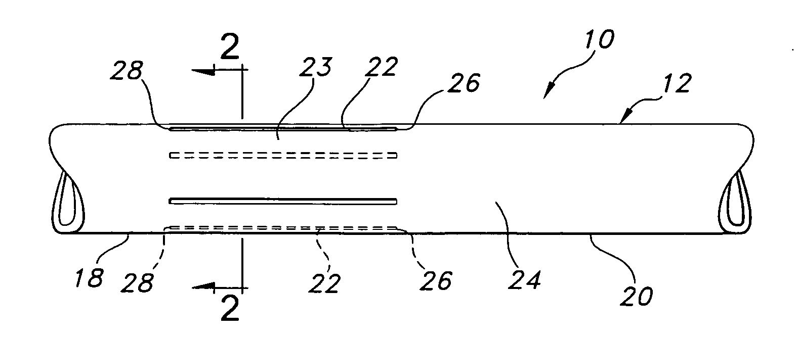
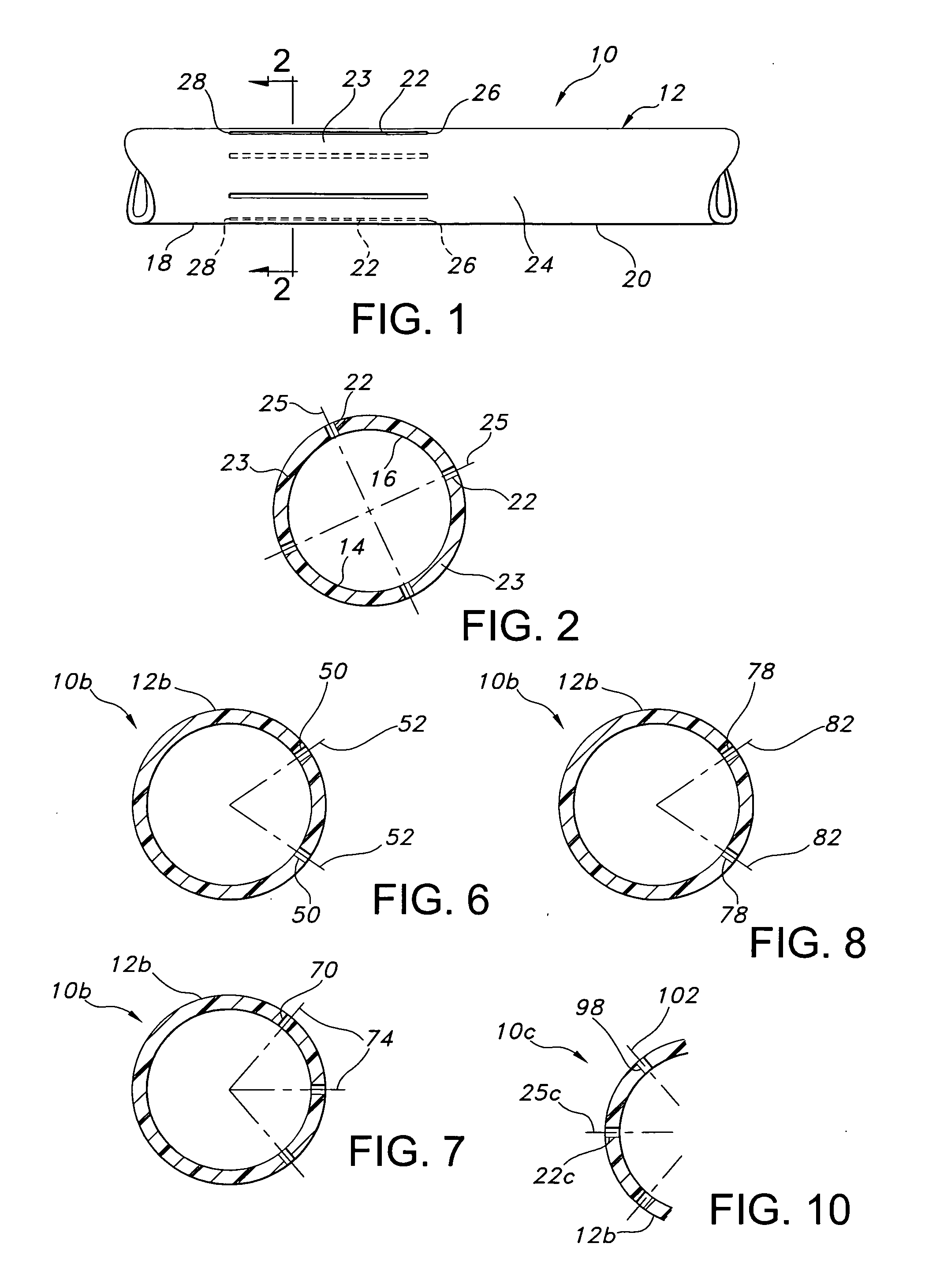
[0029] Referring to the drawings and more particularly to FIG. 1, a vascular graft 10 is shown as including a tube structure 12 having a length and inner and outer wall surfaces 14, 16. The tube structure 12 is formed of polytetrafluoroethylene (PTFE) material.

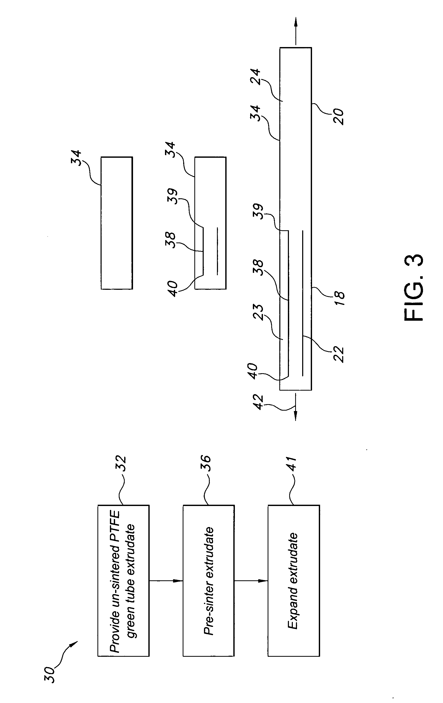
[0030] The tube structure 12 includes first and second longitudinal sections 18, 20. The first longitudinal section 18 includes four non-expanded portions 22 formed from sintering a PTFE green tube extrudate. The region of the first longitudinal section 18, which is not included in the non-expanded portions 22, is expanded such that the first longitudinal section has an expanded portion 23 in addition to the non-expanded portions 22. The second longitudinal section 20 is expanded such that it constitutes another expanded portion 24.

[0031] The non-expanded portions 22 are each elongate and have a longitudinal central axis which is contained in a corresponding longitudinal cross-sectional plane 25 of the PTFE tube structure 12...


PUM

PropertyMeasurementUnit
longitudinal elongationaaaaaaaaaa
elongationsaaaaaaaaaa

Abstract

The vascular graft is for implantation within a body and has a PTFE tube structure including a length and inner and outer wall surfaces. The tube structure has a non-expanded portion formed from sintering a PTFE green tube extrudate and an expanded portion formed subsequent to the sintering. The expanded and non-expanded portions are of the same extrudate. The expanded portion has a region which adjoins the non-expanded portion wherein a degree of expansion of the region is limited by the non-expanded portion. The limiting of the expansion by the non-expanded portion is attenuated at a location of the region which is remote from the non-expanded portion. A method for making the vascular graft facilitates the formation of the non-expanded and expanded portions of the PTFE tube structure.

Description

FIELD OF THE INVENTION [0001] The present invention relates to sintered structures for a vascular graft and, more specifically, to a vascular graft having a PTFE tube structure one or more discrete portions of which are sintered prior to expansion thereof such that such expansion of the PTFE tube structure results in different microstructures thereof at various locations on the PTFE tube structure. BACKGROUND OF THE INVENTION [0002] It is well known to use extruded tube structures of polytetrafluoroethylene (PTFE) as implantable intraluminal prostheses, particularly vascular grafts. PTFE is particularly suitable as an implantable prosthesis as it exhibits superior biocompatibility. PTFE tube structures may be used as vascular grafts in the replacement or repair of a blood vessel as PTFE exhibits low thrombogenicity. In vascular applications, the grafts are manufactured from expanded polytetrafluoroethylene (ePTFE) tube structures. These tube structures have a microporous structure w...

Claims


Application Information

Patent Timeline
Patent Type & Authority Applications(United States)
IPC IPC(8): A61F2/06
CPCA61F2/06A61F2250/0028A61F2250/0048B29C35/0266B29C55/005B29K2027/18B29L2031/7534
Inventor HENDERSON, JAMIE
Owner LIFESHIELD SCI
Why Eureka
Try Eureka