Apparatus and Method for Reducing Carbon Monoxide Emissions

a technology of carbon monoxide and apparatus, which is applied in the direction of engine ignition, lighting and heating apparatus, engine starters, etc., can solve the problems of limiting the amount of revenue that can be generated, other technologies such as catalysts and lower flame temperature combustors can be expensive as well, and save fuel costs, so as to reduce carbon monoxide emissions, reduce reaction processing co emissions, and increase the residence time

Active Publication Date: 2006-07-13
H2 IP UK LTD
View PDF25 Cites 11 Cited by
  • Summary
  • Abstract
  • Description
  • Claims
  • Application Information

AI Technical Summary

Benefits of technology

[0006] The present invention discloses an apparatus and method for reducing the carbon monoxide emissions emitted by a pilot injector of a gas turbine combustor. The pilot injector provides the main flame source for igniting a fuel / air mixture in the combustor and at lower power settings is the only source of hot combustion gases necessary to drive the turbine. The preferred embodiment of the pilot injector comprises a radial swirler, at least one fuel injector, a passageway formed between first and second spaced walls, a means for establishing a recirculation area adjacent to the pilot injector, and a generally annular extension protruding into the combustor thereby providing a region for the CO to burnout prior to interacting with surrounding air flows and becoming quenched. It is in this recirculation area, of lower pressure, that the pilot flame will anchor and burn. As a result, the pilot flame is anchored separate from the main fuel air mixture, which would quench the reaction processing CO emissions from the pilot flame. Furthermore, the pilot flame is anchored further upstream so as to establish a greater residence time in which the pilot flame is to burn and complete the reactions to minimize CO formation.

Problems solved by technology

The latter is the most unfavorable option as it limits the amount of revenue that can be generated.
However, the other technologies such as a catalyst and lower flame temperature combustors can be expensive as well.
However, there are many times when power demand is lower and it is more desirable to operate at a lower power setting, such that only the power demanded is actually supplied, thereby saving on fuel costs.
It has been determined that when powerplants operate at conditions other than their most efficient, or design point, emission levels can go out of compliance with local regulations.
Carbon monoxide from gas turbine combustion systems can typically be caused by a number of factors including inadequate burning rates, inadequate mixing of fuel and air prior to combustion, or quenching of the combustion products in surrounding cooling air.
At these lower power settings, the combustion systems are operating at a lower fuel flow and often times burning in a different region than that of the full power condition that may not be as efficient.

Method used


Image

  • Apparatus and Method for Reducing Carbon Monoxide Emissions
  • Apparatus and Method for Reducing Carbon Monoxide Emissions
  • Apparatus and Method for Reducing Carbon Monoxide Emissions

Examples


Embodiment Construction

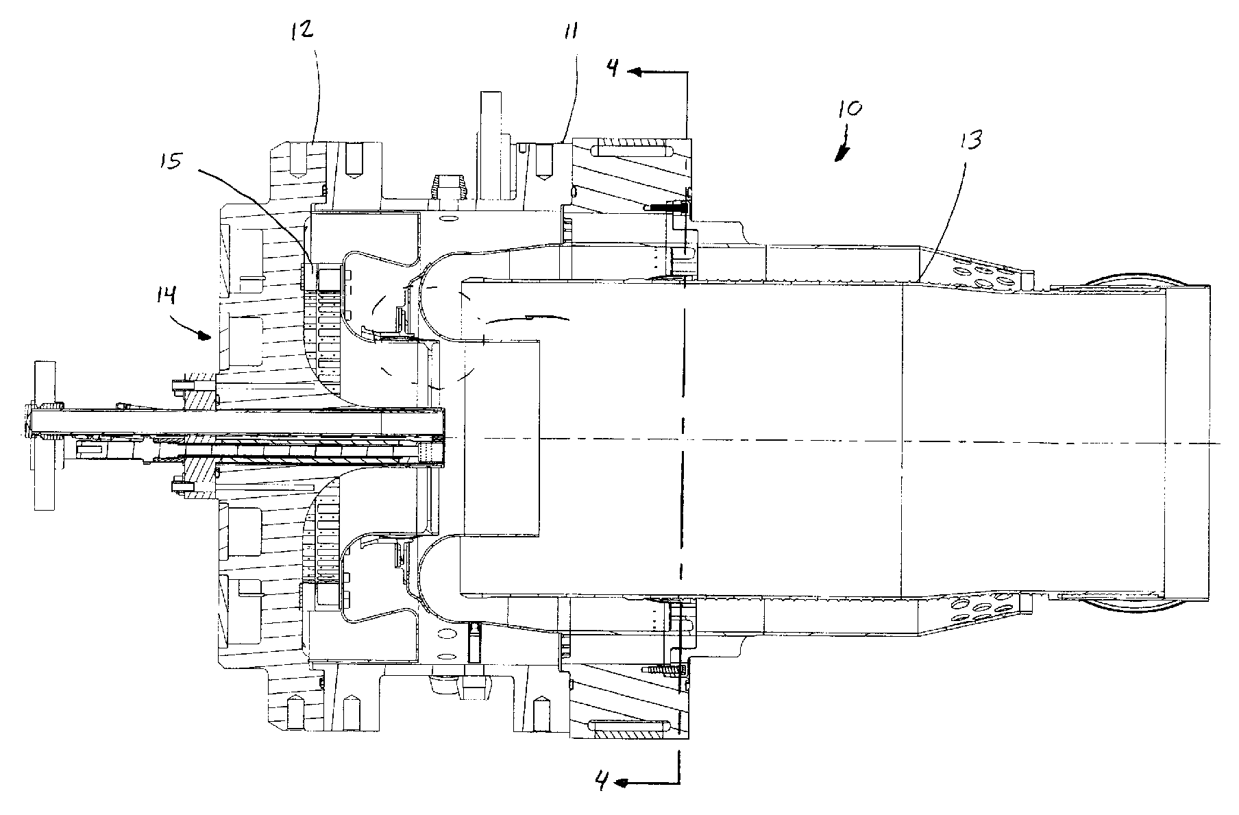
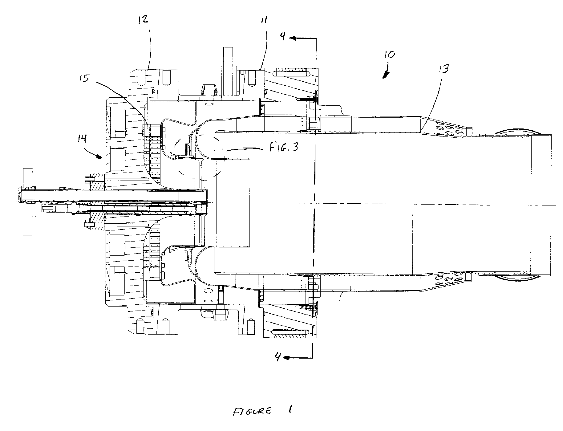
[0015] The present invention will now be described in detail with reference to FIGS. 1-8. Referring now to FIG. 1, a gas turbine combustor having a pilot injector in accordance with the present invention is shown in cross section. Combustor 10 comprises a casing 11, an end cover 12, a liner 13, and a pilot injector 14. The pilot injector is placed proximate the forward end of combustor 10 in order to provide the fuel source to establish a pilot flame in liner 13. Pilot injector 14, which is shown in greater detail in FIGS. 2 and 3, comprises a radial swirler 15, a first wall 16, and a second wall 17 in spaced relation such that a passageway 18 is formed therebetween. Passageway 18 has an inlet 19 and an outlet 20 and is oriented generally radially proximate inlet 19 and generally axially proximate outlet 20. Adjacent pilot injector 14, proximate outlet 20, but within passageway 18, is a means for establishing a recirculation area 21. Pilot injector 14 also comprises at least one fue...


PUM


Abstract

The present invention discloses an apparatus and method for reducing the carbon monoxide emissions emitted by a pilot injector of a gas turbine combustor. Multiple embodiments of a means for establishing a recirculation zone are disclosed whereby a portion of the fuel and air mixture from the pilot injector recirculates and a flame is held, thereby increasing the local reaction temperature at the desired location and lowering carbon monoxide emissions.

Description

BACKGROUND OF THE INVENTION [0001] The present invention relates generally to gas turbine combustors and more specifically to an apparatus and method for reducing carbon monoxide emissions from gas turbine combustors. [0002] In recent years government officials have passed more restrictive regulations regarding powerplant emissions, especially those for oxides of nitrogen (NOx) and carbon monoxide (CO). Each of these emissions are well known to contribute to air pollution and regulators continue to set lower levels of acceptable emissions. There are various means to comply with these lower emissions requirements, which vary depending on the powerplant location. Such means include passing the exhaust gases through a catalyst, which serves to transform the carbon monoxide and remaining hydrocarbons into water and carbon dioxide, utilizing lower flame temperature combustors, or limiting the amount of operating time of the powerplant. The latter is the most unfavorable option as it limi...

Claims


Application Information

Patent Timeline
Patent Type & Authority Applications(United States)
IPC IPC(8): F23R3/30
CPCF23C9/006F23R3/16F23R3/343
Inventor OUMEJJOUD, KHALIDSTUTTAFORD, PETERCHEN, YANMARGARIT-BEL, NURIAJENNINGS, STEPHEN
Owner H2 IP UK LTD
Why Eureka
Try Eureka