
Method and apparatus for highly efficient compact vapor compression cooling

a compact, vapor compression technology, applied in the direction of domestic cooling apparatus, lighting and heating apparatus, liquid fuel engines, etc., can solve the problem that the performance of this system cannot be matched simply, and achieve the effect of high coefficient of performan

Inactive Publication Date: 2006-07-13
RINI TECH
View PDF20 Cites 3 Cited by
  • Summary
  • Abstract
  • Description
  • Claims
  • Application Information

AI Technical Summary

Benefits of technology

[0010] The subject system can be scaled to larger or smaller sizes for different applications. The subject system can incorporate a compressor and condenser design so as to achieve a high coefficient of performance and a light and compact design. A compressor can be a key component with respect to the overall performance of a vapor compression system, whereas a condenser can be a key component with respect to the overall weight and size. The subject cooling system can also utilize a miniaturized high efficiency motor design, along with integration of a compact heat exchanger for refrigerant evaporation and liquid pump.

Problems solved by technology

The performance of this system cannot be matched simply by using smaller versions of currently available designs.

Method used


Image

  • Method and apparatus for highly efficient compact vapor compression cooling
  • Method and apparatus for highly efficient compact vapor compression cooling
  • Method and apparatus for highly efficient compact vapor compression cooling

Examples


Embodiment Construction

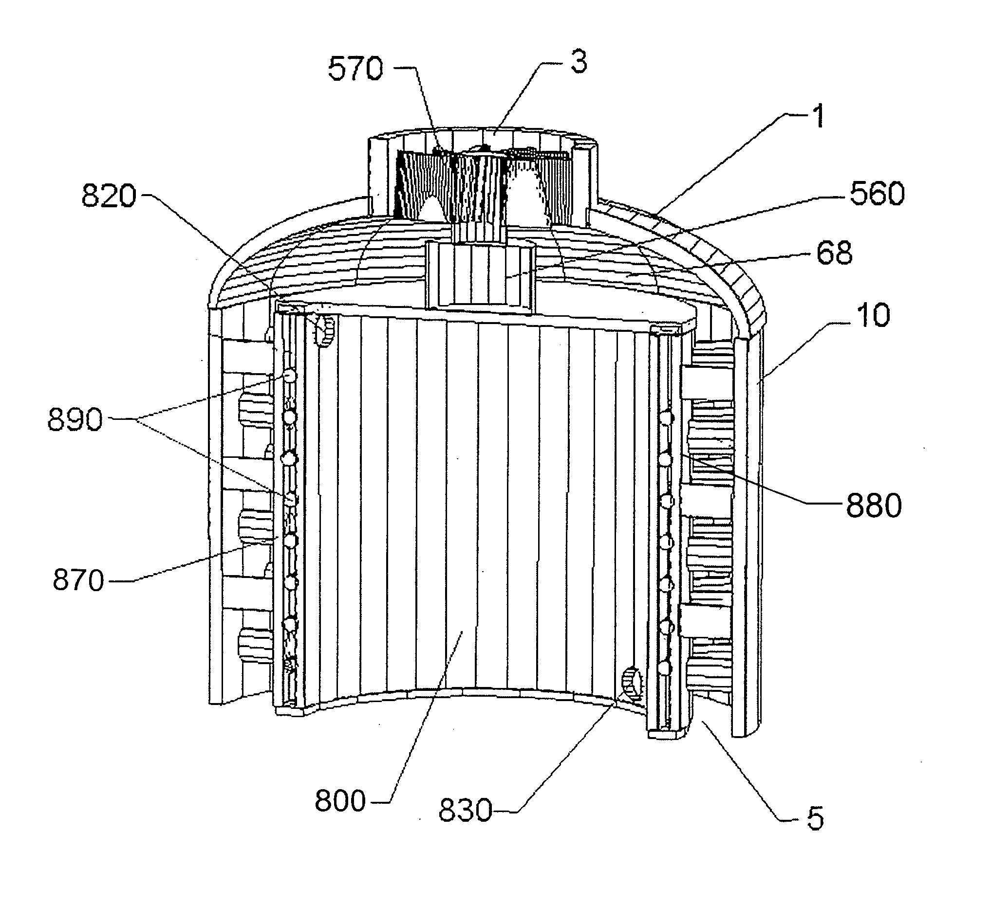
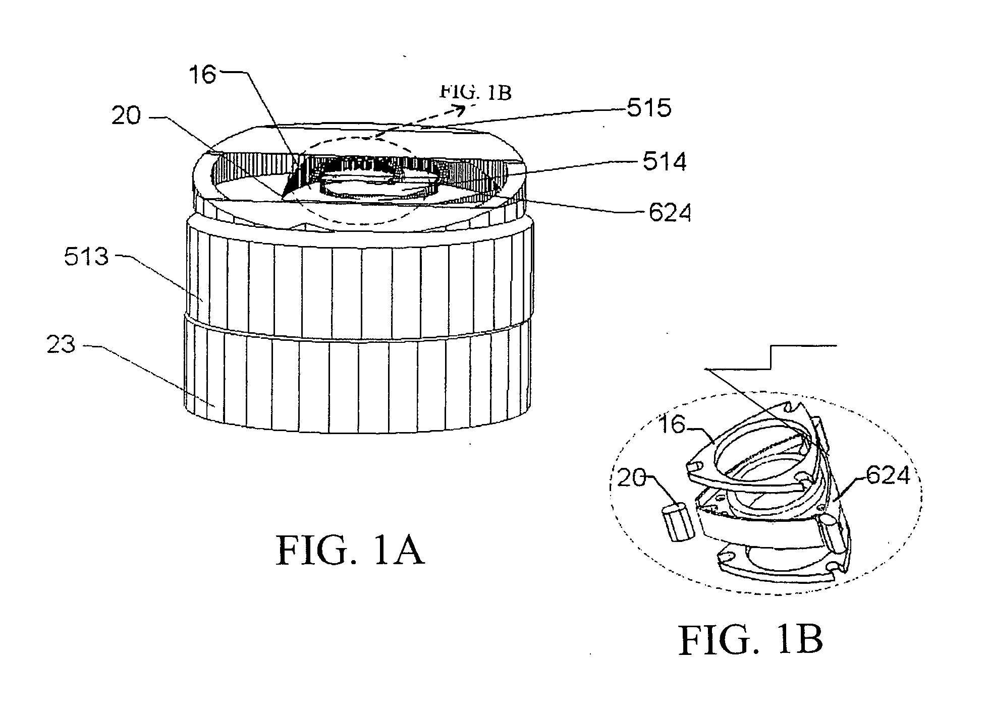
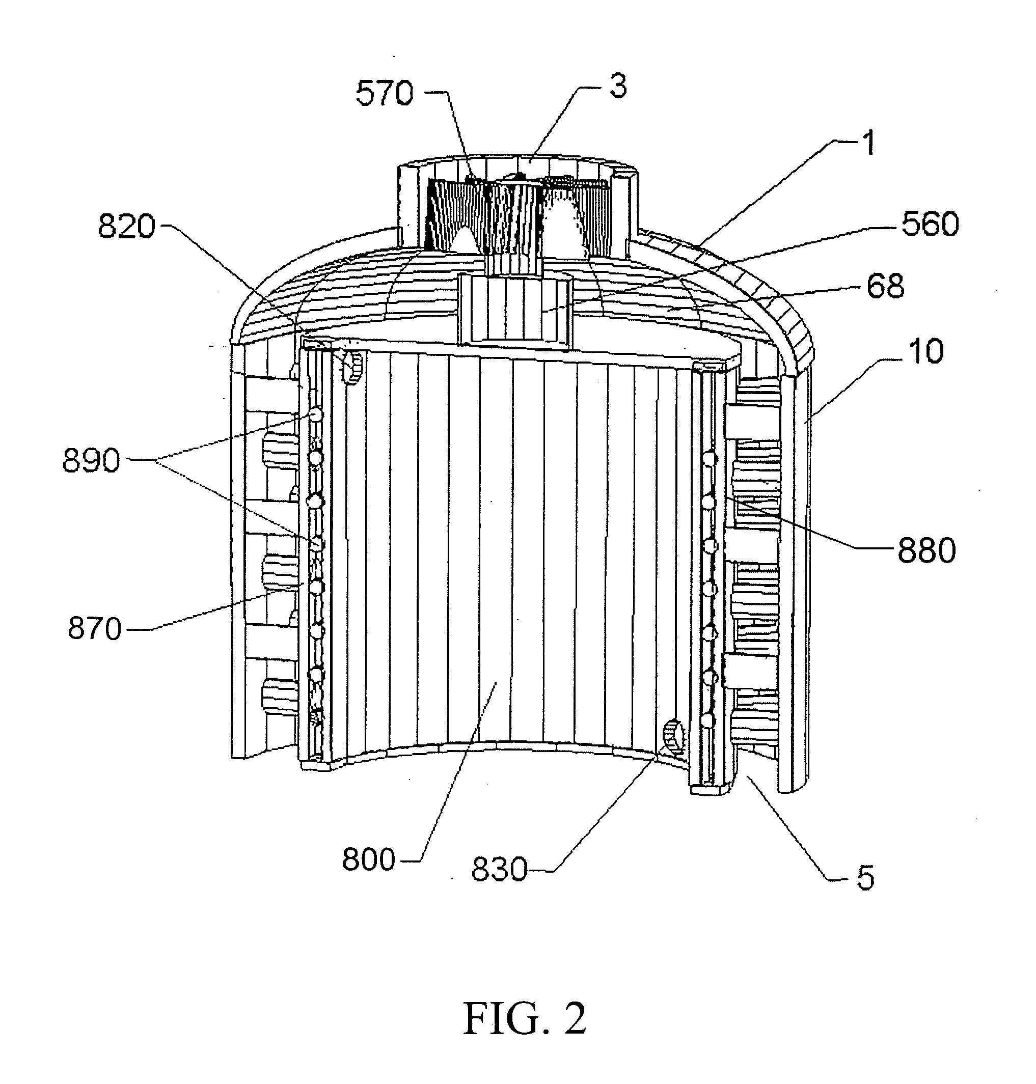
[0031] The subject invention pertains to a method and apparatus for cooling. In a specific embodiment, the subject invention relates to a lightweight, compact, reliable, and efficient cooling system. The subject system can provide heat stress relief to individuals operating under, for example, hazardous conditions, or in elevated temperatures while wearing protective clothing. The subject system can be utilized in other applications that can benefit from this type of cooling system. The performance of this system cannot be matched simply by using smaller versions of currently available designs.

[0032] The subject invention also relates to a condenser for transferring heat from a refrigerant to an external fluid in thermal contact with the condenser. The subject condenser can have a heat transfer surface and can be designed for an external fluid, such as air, to flow across the heat transfer surface and allow the transfer of heat from heat transfer surface to the external fluid. In a...


PUM


Abstract

The subject invention pertains to a method and apparatus for cooling. In a specific embodiment, the subject invention relates to a lightweight, compact, reliable, and efficient cooling system. The subject system can provide heat stress relief to individuals operating under, for example, hazardous conditions, or in elevated temperatures, while wearing protective clothing. The subject invention also relates to a condenser for transferring heat from a refrigerant to an external fluid in thermal contact with the condenser. The subject condenser can have a heat transfer surface and can be designed for an external fluid, such as air, to flow across the heat transfer surface and allow the transfer of heat from heat transfer surface to the external fluid. In a specific embodiment, the flow of the external fluid is parallel to the heat transfer surface. In another specific embodiment, the heat transfer surface can incorporate surface enhancements which enhance the transfer of heat from the heat transfer surface to the external fluid. In another specific embodiment, an outer layer can be positioned above the heat transfer surface to create a volume between the heat transfer surface and the outer layer through which the external fluid can flow.

Description

CROSS-REFERENCE TO RELATED APPLICATION [0001] The present application is a divisional application of U.S. application Ser. No. 10 / 625,014, filed Jul. 22, 2003, which claims the benefit of U.S. Provisional Application Ser. No. 60 / 413,056, filed Sep. 24, 2002, both of which are hereby incorporated by reference herein in their entirety, including any figures, tables, or drawings.BACKGROUND OF THE INVENTION [0002] The subject invention relates to microclimate cooling, and a miniature cooling system that can be used for any purpose that requires a compact cooling system. Such applications include, but are not limited to, microelectronics cooling such as computer processors and laser diodes, personal cooling systems, and portable cooling systems. [0003] Clothing that protects soldiers, first responders, and other emergency personnel from chemical, biological, nuclear, and / or other similar threats can subject the individuals to heat stress. Certain hazardous environments can require the us...

Claims


Application Information

Patent Timeline
Patent Type & Authority Applications(United States)
IPC IPC(8): F25D17/06F25B39/04F04C18/22F04C23/00F04C29/04F25B1/00F25B1/04F25B39/02F28B1/06F28D7/02F28D9/04F28F1/12
CPCF04C18/22F04C23/00F04C23/008F04C29/04F25B1/005F25B1/04F25B39/02F25B39/04F28B1/06F28D7/026F28D9/04F28F1/124
Inventor RINI, DANIEL P.CHOW, LOUISANDERSON, H. RANDOLPHKAPAT, JAYANTA SANKARCARMAN, BRADLEYGULLIVER, BRIANRECIO, JOSE MAURICIO
Owner RINI TECH
Learn More