Timing cover for engine

a timing cover and engine technology, applied in the direction of machines/engines, mechanical equipment, casings, etc., can solve the problems of engine vibration and noise, other vibration and noise, and another vibration and noise at a different frequency band, so as to reduce the generation of vibration and strengthen the structural rigidity

Inactive Publication Date: 2006-07-13
HYUNDAI MOTOR CO LTD
View PDF3 Cites 8 Cited by
  • Summary
  • Abstract
  • Description
  • Claims
  • Application Information

AI Technical Summary

Benefits of technology

[0018] Since a plurality of dome-shaped embossed portions are formed at positions of the timing cover which are proved to be the most susceptible to vibration through the analysis of vibration modes of the timing cover, the timing cover of the present invention has a high characteristic frequency, thereby avoiding a frequency band generated from the engine during driving a

Problems solved by technology

During driving, the engine generates vibration and noise due to periodic variations in a central position according to the vertical motion of a piston and a connecting rod.
The above vibration and noise generated from the engine due to the above variations affect other peripheral components located around the engine, thereby causing other vibrations and noises.
The characteristic vibration and noise generated from the driving of the timing belt or the timing chain causes another vibration and no

Method used


Image

  • Timing cover for engine
  • Timing cover for engine
  • Timing cover for engine

Examples


Embodiment Construction

[0027] Exemplary embodiments of the present invention will be described in more detail with reference to the annexed drawings.

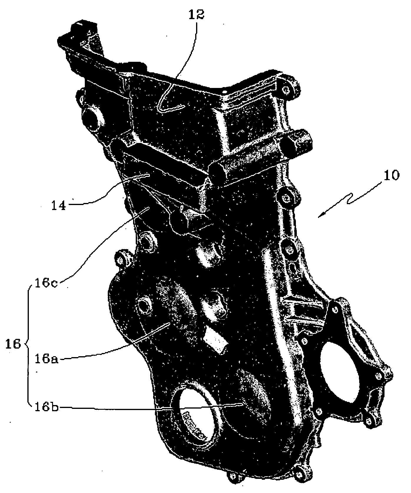
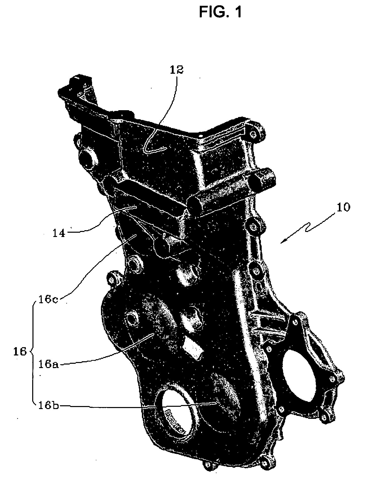
[0028]FIG. 1 illustrates the timing cover 10 connected to one side of a cylinder block (not shown). The timing cover 10 comprises a cover portion 12 formed on the upper end thereof for covering a continuous variable valve timing device, and a support bracket 14 protruded outwardly from the lower portion for mounting an engine mount (not shown). Here, the cover portion 12 and the support bracket 14 may be integrally formed.

[0029] A timing cover 10 having the above structure is provided with a front surface connected to one side of the cylinder block, and covers a sprocket (not shown) installed on a crank shaft, a sprocket (not shown) installed on a cam shaft, and a timing belt or a timing chain (not shown) for interlocking the sprockets.

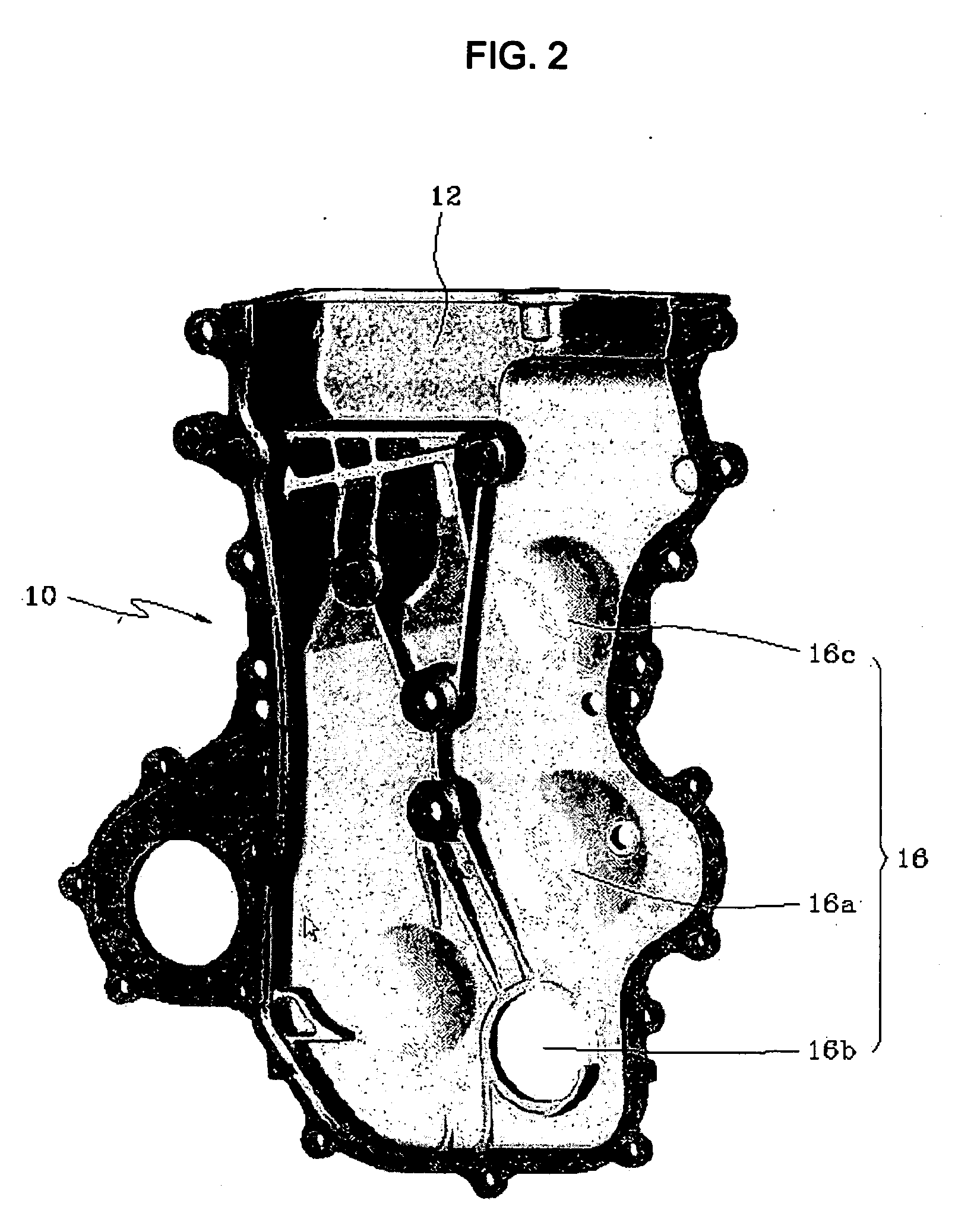
[0030] A plurality of embossed portions 16 having a hemispheric dome shape are formed on the timing cover 10. The embossed...


PUM


Abstract

A timing cover for an engine includes a plurality of dome-shaped embossed portions formed at positions of the timing cover that are most susceptible to vibration, based on an analysis of vibration modes of the timing cover.

Description

CROSS-REFERENCE TO RELATED APPLICATION [0001] This application claims priority to and the benefit of Korean Patent Application No. 10-2004-0110757 filed in the Korean Intellectual Property Office on Dec. 22, 2004, the entire contents of which are incorporated herein by reference. BACKGROUND OF THE INVENTION [0002] 1. Field of the Invention [0003] The present invention relates to a timing cover for an engine, and more particularly to a timing cover with a high characteristic frequency band. [0004] 2. Description of the Related Art [0005] Generally, an engine for a vehicle serves as a power generating device. The engine draws a fuel-air mixture into a combustion chamber by the operation of a suction system and a fuel system, and bums the fuel-air mixture by the operation of a combustion system, thereby generating driving force necessary to drive the vehicle. [0006] During driving, the engine generates vibration and noise due to periodic variations in a central position according to th...

Claims


Application Information

Patent Timeline
IPC IPC(8): F02B77/00
CPCF02F7/0073F02F7/008F02F2007/0078F02B67/06F02B77/13
Inventor SHIN, BO SUNG
Owner HYUNDAI MOTOR CO LTD
Why Eureka
Try Eureka