Device for reducing vehicle aerodynamic resistance

Active Publication Date: 2006-07-13
FREIGHT WING
View PDF13 Cites 84 Cited by
  • Summary
  • Abstract
  • Description
  • Claims
  • Application Information

AI Technical Summary

Benefits of technology

[0004] In general, a device for reducing vehicle aerodynamic resistance disposed on the bottom of a vehicle having a generally rectangular body disposed above rear wheels, when made in accordance with this invention, comprises a plurality of load bearing struts of a predetermined size attached to the bottom of the rectangular body adjacent the sides thereof which can absorb impact in the event of a side collision. A plurality of impact absorbing members extending between adjacent load bearing struts and fastened thereto which can absorb impact in the event of a side collision. A plurality of opposing flat sheets attached to the load bearing struts. Front opposed flat sheets disposed toward the front of the rectangular body, intermediate opposed flat sheets disposed behind the front opposed flat sheets, and rear opposed flat shee

Problems solved by technology

It is well known that streamlining the undercarriage of a long vehicle such as a trailer truck or straight van truck will reduce the aerodynamic resistance of a moving vehicle and thus save fuel.
However, streamlining the undercarriage of a long vehicle such as a semi-trailer is impractical because integrated enclosures are heavy, costly, easily damaged, interfere with standardized structural design, and prevent access to parts and equipment underneath the vehicle.
However, past designs for removable attachments have failed to achieve significant utilization because they are typically large and heavy enclosures or one piece structures, which are difficult to transport when not mounted on the trailer, difficult to mount, require drilling or I welding the undercarriage when mounting, incompatible with different trailer and truck geometries, easily damaged, difficult to repair, become filled with snow and ice in winter driving conditions, do n

Method used


Image

  • Device for reducing vehicle aerodynamic resistance
  • Device for reducing vehicle aerodynamic resistance
  • Device for reducing vehicle aerodynamic resistance

Examples


Example

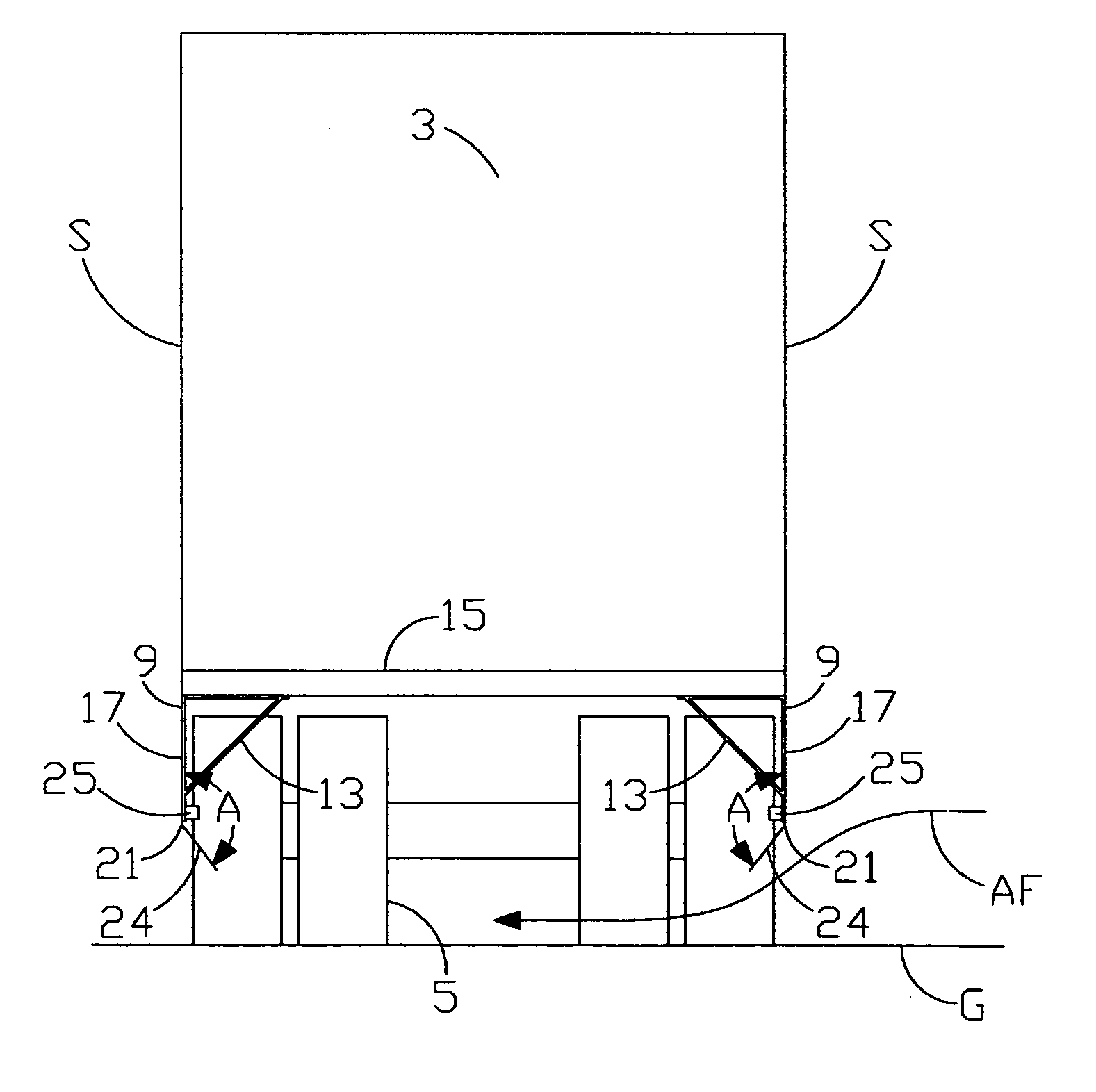
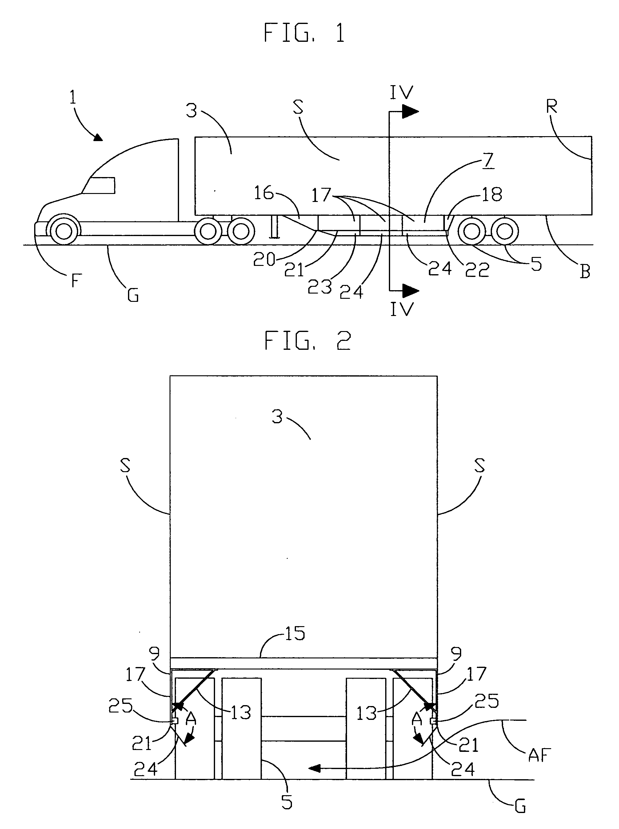
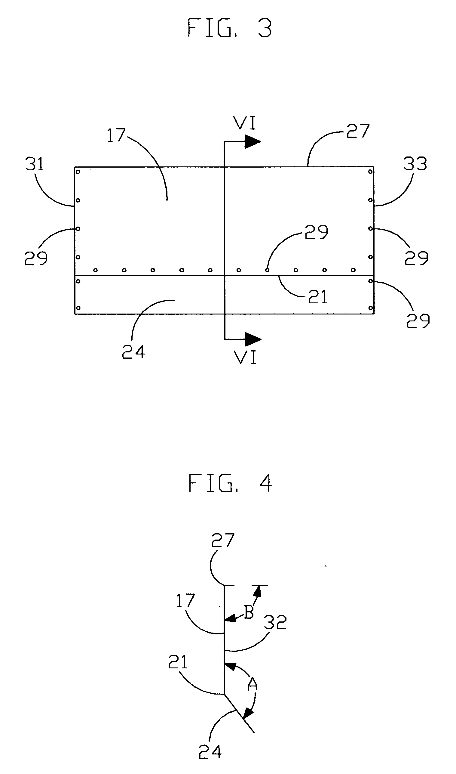
[0015] Referring now to the drawings in detail and in particular to FIGS. 1 and 2, there is shown a vehicle 1 such as a trailer truck, having a generally rectangular body 3 having a front F, rear R, bottom B and opposed sides S mounted above rear wheels 5 and a device 7 for reducing the aerodynamic resistance of the vehicle 1 when it moves. The device 7 comprises a pair of opposed airfoils 9 disposed beneath the rectangular body 3 adjacent its sides S and are preferably made of aluminum, but of course other material could be utilized. Each opposing airfoil comprises load bearing struts 13, which are removably attached to the vehicle cross members 15. The load bearing struts 13 having predetermined dimensions are designed to carry loads from different directions and absorb impact from side collisions. They are shown fabricated from strips of flat sheets bent and joined to form a triangle. Opposed flat sheets 16, 17 and 18 are attached to the load bearing struts 13 adjacent the sides ...


PUM


Abstract

A device for reducing vehicle aerodynamic resistance for vehicles having a generally rectangular body disposed above rear wheels, comprising a plurality of load bearing struts attached to the bottom of the rectangular body adjacent its sides, a plurality of opposing flat sheets attached to the load bearing struts, and angled flaps attached to the lower edge of the opposing sheets defining an obtuse angle with the opposing flat sheets extending inwardly with respect to the sides of the rectangular body to a predetermined height above the ground, which, stiffen the opposing flat sheets, bend to resist damage when struck by the ground, and guide airflow around the rear wheels of the vehicle to reduce its aerodynamic resistance when moving.

Description

[0001] This invention was made with Government support under Contract No. DE-FC36-03G013173 awarded by the Department of Energy. The Government has certain rights in this invention.TECHNICAL FIELD [0002] The invention relates to a device for reducing the aerodynamic resistance of a moving, rectangular shaped vehicle and more particularly to a pair of opposing airfoils that are mounted underneath the vehicle adjacent its sides. BACKGROUND ART [0003] It is well known that streamlining the undercarriage of a long vehicle such as a trailer truck or straight van truck will reduce the aerodynamic resistance of a moving vehicle and thus save fuel. However, streamlining the undercarriage of a long vehicle such as a semi-trailer is impractical because integrated enclosures are heavy, costly, easily damaged, interfere with standardized structural design, and prevent access to parts and equipment underneath the vehicle. Consequently, removable attachments have been designed to streamline the u...

Claims


Application Information

Patent Timeline
IPC IPC(8): B62D35/02B60R99/00
CPCB60R19/565B62D35/001
Inventor GRAHAM, SEAN C.
Owner FREIGHT WING
Why Eureka
Try Eureka