Doherty microwave amplifier and signal processing method thereof

a microwave amplifier and amplifier technology, applied in the direction of amplifiers, amplifiers with semiconductor devices only, amplifiers with semiconductor devices, etc., can solve the problems that the existing doherty amplifier cannot accurately perform linear compensation, and cannot achieve accurate linearity

Inactive Publication Date: 2006-07-13
KK TOSHIBA
View PDF8 Cites 27 Cited by
  • Summary
  • Abstract
  • Description
  • Claims
  • Application Information

AI Technical Summary

Benefits of technology

[0003] The present invention relates to a Doherty microwave amplifier (hereinafter, referred to as Doherty amplifier) and a signal processing method thereof.
[0012] Additional advantages of the invention will be set forth in the description which follows, and in part will be obvious from the description, or may be learned by practice of the invention. The advantages of the invention may be realized and obtained by means of the instrumentalities and combinations particularly pointed out hereinafter.

Problems solved by technology

And the existing Doherty amplifier becomes impossible to accurately perform the linear compensation also depending on the individual difference in the main amplifier 100.
Therefore, influence of a change in temperature or individual difference in Doherty amplifiers causes the problem that accurate linearity can not be obtained.

Method used


Image

  • Doherty microwave amplifier and signal processing method thereof
  • Doherty microwave amplifier and signal processing method thereof
  • Doherty microwave amplifier and signal processing method thereof

Examples


first embodiment

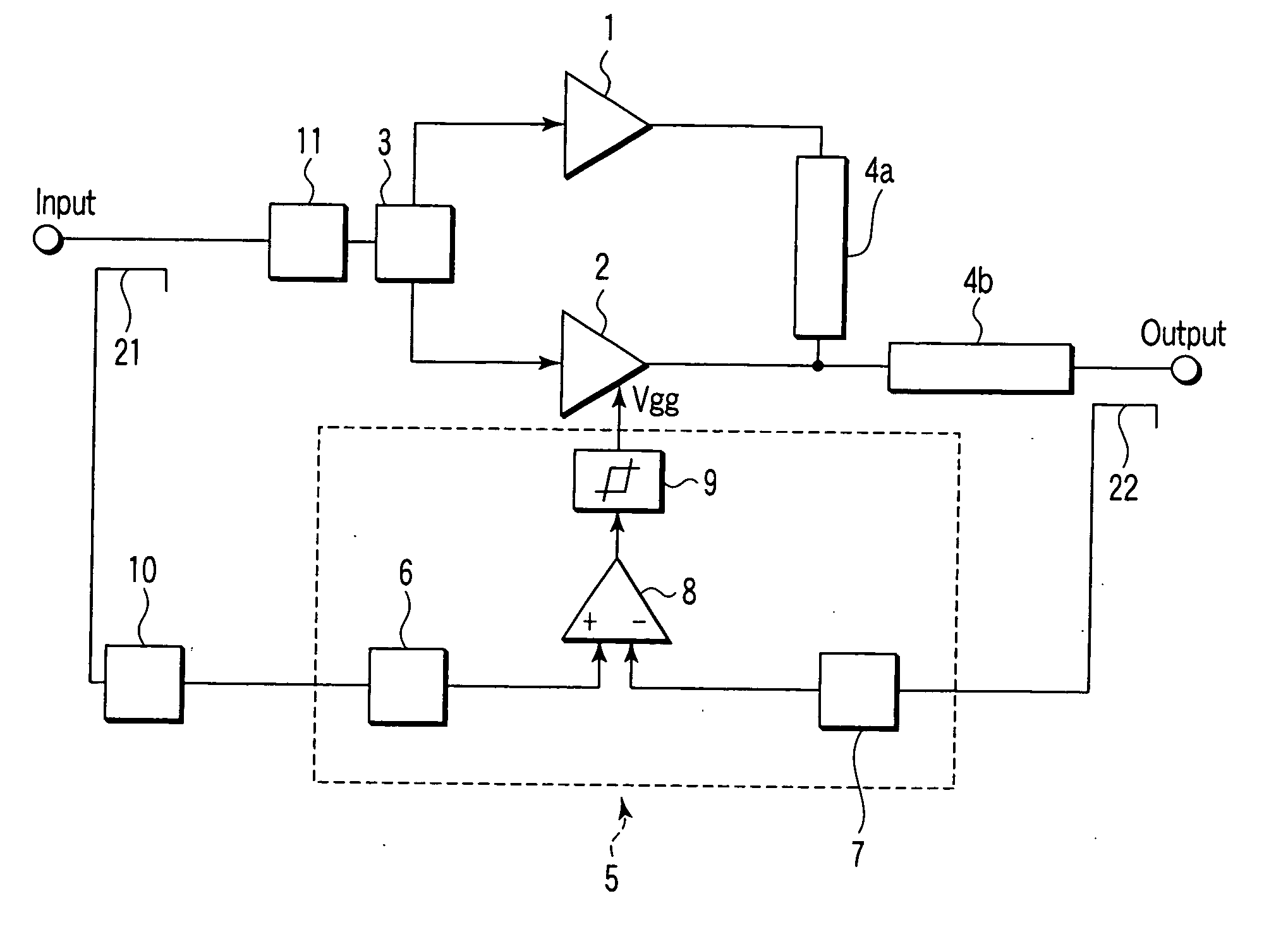
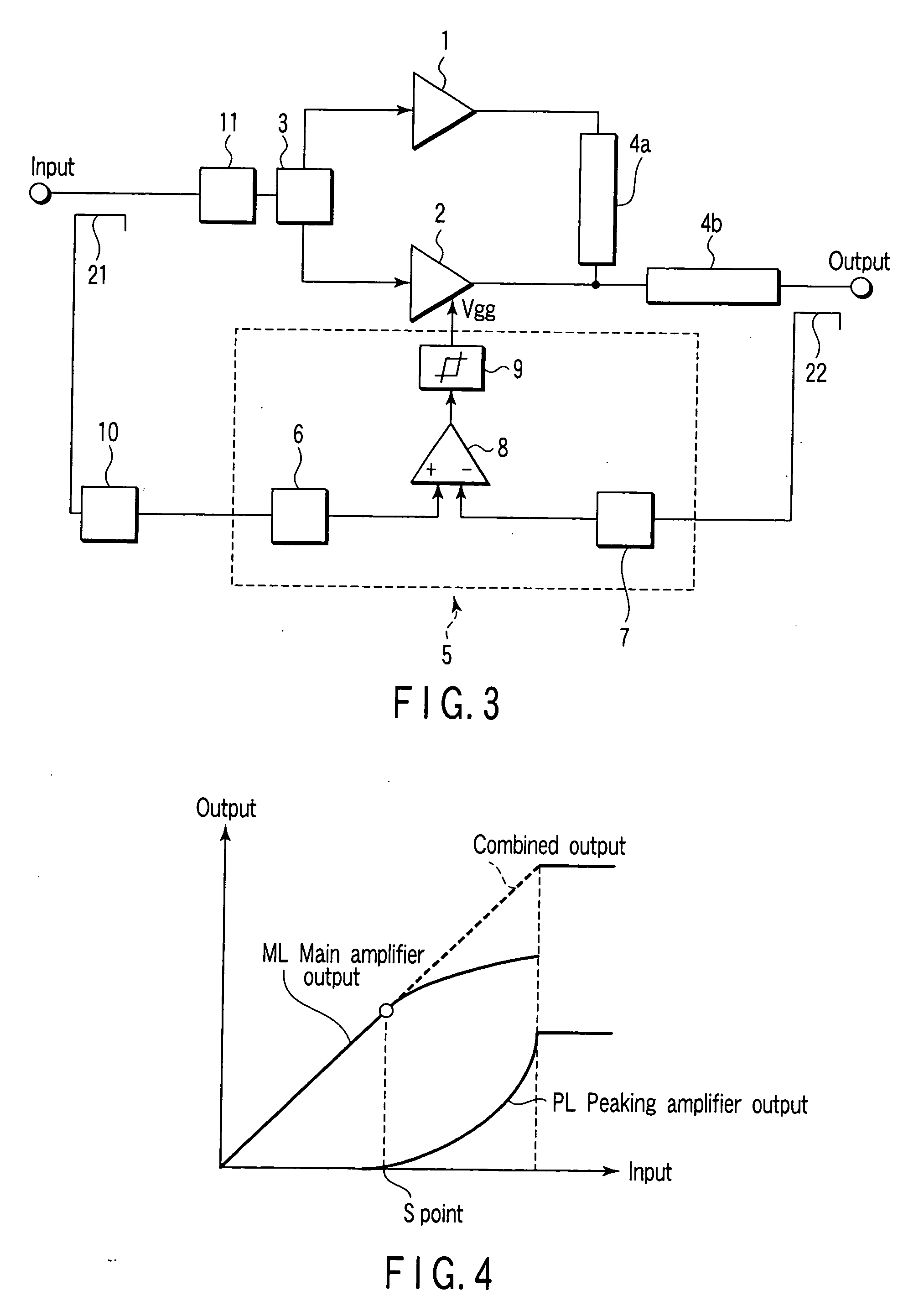
[0025]FIG. 3 is the exemplary block diagram showing the first embodiment of the Doherty amplifier regarding the present invention. FIG. 4 is the exemplary view showing the input / output characteristic of the Doherty amplifier in FIG. 3. A configuration and an operation of the Doherty amplifier regarding the first embodiment of the present invention will be described by referring to FIG. 3 and FIG. 4.

[0026] In FIG. 3, the Doherty amplifier comprises a main amplifier 1, a peaking amplifier 2, a distributor 3, a ¼ wave length impedance converter 4a, a ¼ wave length impedance converter 4b, a bias control unit 5, a delay unit 10 and a temperature compensation attenuator 11. The bias control unit 5 comprises a detector 6, a detector 7, a level comparator 8 and an amplitude limiter 9. An input and an output are provided with couplers 21 and 22 in order to branch each signal to the level comparator 8, respectively.

[0027] In the Doherty amplifier regarding the first embodiment, the level co...

second embodiment

[0039]FIG. 5 the exemplary block diagram showing the second embodiment of the Doherty amplifier regarding the present invention. FIG. 6 is the exemplary view showing the input / output characteristic of the Doherty amplifier in FIG. 5. The Doherty amplifier in FIG. 5 comprises peaking amplifiers 2a and 2b. A bias control unit 5 comprises level comparators 8a and 8b, amplitude limiters 9a and 9b and a ¼ wave length impedance converter 4c.

[0040] The ¼ wavelength impedance converter 4c connected to the output from the peaking amplifier 2b is further added to the output of the ¼ wavelength impedance converter 4b of the peaking amplifier 2a. Therefore, the output form the Doherty amplifier becomes the combined output of the main amplifier 1 and two peaking amplifiers 2a and 2b.

[0041] In the second embodiment, the combined output is input to the level comparator 8b through the detector 7. The level comparator 8b outputs a gate voltage Vggb to the peaking amplifier 2b and one input termina...

third embodiment

[0049] The first embodiment of the present invention can realize a high-efficiency amplifier superior to amplitude linearity. The second embodiment of the present invention can realize a Doherty type high-efficiency amplifier capable of retain a response time in high by a parallel use of low-output peaking amplifiers 2.

[0050] In the meantime, it is important for a high-frequency such as a microwave to retain constant in not only a response time but also a phase characteristic in accordance with an output. Therefore, in the third embodiment of the present invention, a configuration capable of obtaining an output with a constant phase characteristic even if not only an amplitude characteristic but also an output amplitude have changed (in other word, change in input amplitude) will be described.

[0051]FIG. 7 is the exemplary block diagram showing the third embodiment of the Doherty amplifier regarding the present invention. The Doherty amplifier in FIG. 7 has a configuration in which...


PUM


Abstract

A Doherty microwave amplifier having a main amplifier and a peaking amplifier, distributing and inputting an input signal to the main amplifier and the peaking amplifier to obtain an output signal by combining an output from the main amplifier and an output from the peaking amplifier, comprises a first coupler which branches and outputs a part of the input signal, a second coupler which branches and outputs a part of the output signal, and a bias control unit which feedback-controls a bias signal to the peaking amplifier, based on a difference between a level of a signal branched and output from the first coupler and a level of a signal branched and output from the second coupler.

Description

CROSS-REFERENCE TO RELATED APPLICATIONS [0001] This application is based upon and claims the benefit of priority from prior Japanese Patent Application No. 2004-359705, filed Dec. 13, 2004, the entire contents of which are incorporated herein by reference. BACKGROUND OF THE INVENTION [0002] 1. Field of the Invention [0003] The present invention relates to a Doherty microwave amplifier (hereinafter, referred to as Doherty amplifier) and a signal processing method thereof. [0004] 2. Description of the Related Art [0005] A Doherty amplifier is well known as an amplifier with high efficiency. The Doherty amplifier equipped with a main amplifier to perform linear amplification and a peaking amplifier to compensate deterioration in linearity of the main amplifier in a higher output area. Since the Doherty amplifier can obtain a large output by low power, it has been used even in a high-frequency area such as a microwave (refer to, for example, R. J. McMorrow, D. M. Voton, and P. R. Malonn...

Claims


Application Information

Patent Timeline
Patent Type & Authority Applications(United States)
IPC IPC(8): H03F3/68
CPCH03F1/0288H03F1/32H03F1/3241H03F1/3247H03G3/3042
Inventor KIJIMA, TOORU
Owner KK TOSHIBA
Why Eureka
Try Eureka