
Method and system for driving pixel in active matrix display

a technology of active matrix and pixel, which is applied in the direction of static indicating devices, instruments, cathode-ray tube indicators, etc., can solve the problems of difficult to achieve the above standard, limited color level and brightness in the display, and low luminous efficacy, so as to enhance the brightness of the sub-pixel and achieve the effect of low luminous efficacy and high luminous efficacy

Inactive Publication Date: 2006-07-13
DELTA OPTOELECTRONICS
View PDF20 Cites 45 Cited by
  • Summary
  • Abstract
  • Description
  • Claims
  • Application Information

AI Technical Summary

Benefits of technology

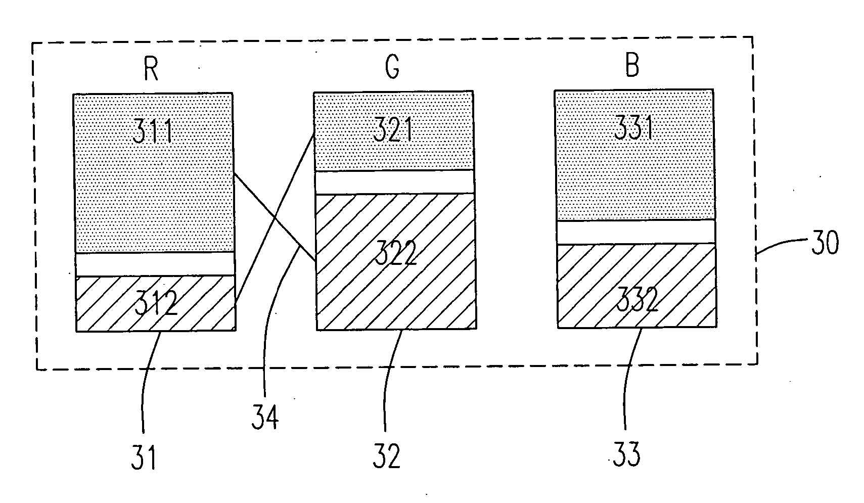
[0014] It is therefore a first aspect of the present invention to provide a method and a system for driving a plurality of pixels in an active matrix display, in which two sub-pixels with different luminous efficacy are electrically connected with each other so as to drive one sub-pixel with a relatively lower luminous efficacy for light-emitting by a drive circuit in another sub-pixel with a relatively higher luminous efficacy, whereby enhancing the brightness of the sub-pixel with a relatively lower luminous efficacy.
[0015] It is therefore a second aspect of the present invention to provide a method and a system for driving a plurality of pixels in an active matrix display including a specific layout of sub-pixels in single pixel to enhance the brightness and the lifetime in the display without changing the sizes of the sub-pixels in the single pixel.
[0018] Preferably, the step (a) is performed by decreasing a depth-to-width ratio (W / L) of a transistor channel in the TFT, so as to provide a relatively lower current density of the first driving current.
[0019] Preferably, the step (b) is performed by increasing a depth-to-width ratio (W / L) of a transistor channel in the TFT, so as to provide a relatively higher current density of the second driving current.
[0043] Preferably, the method further includes a step of decreasing a first driving current generated from the first drive circuit of the first sub-pixel.

Problems solved by technology

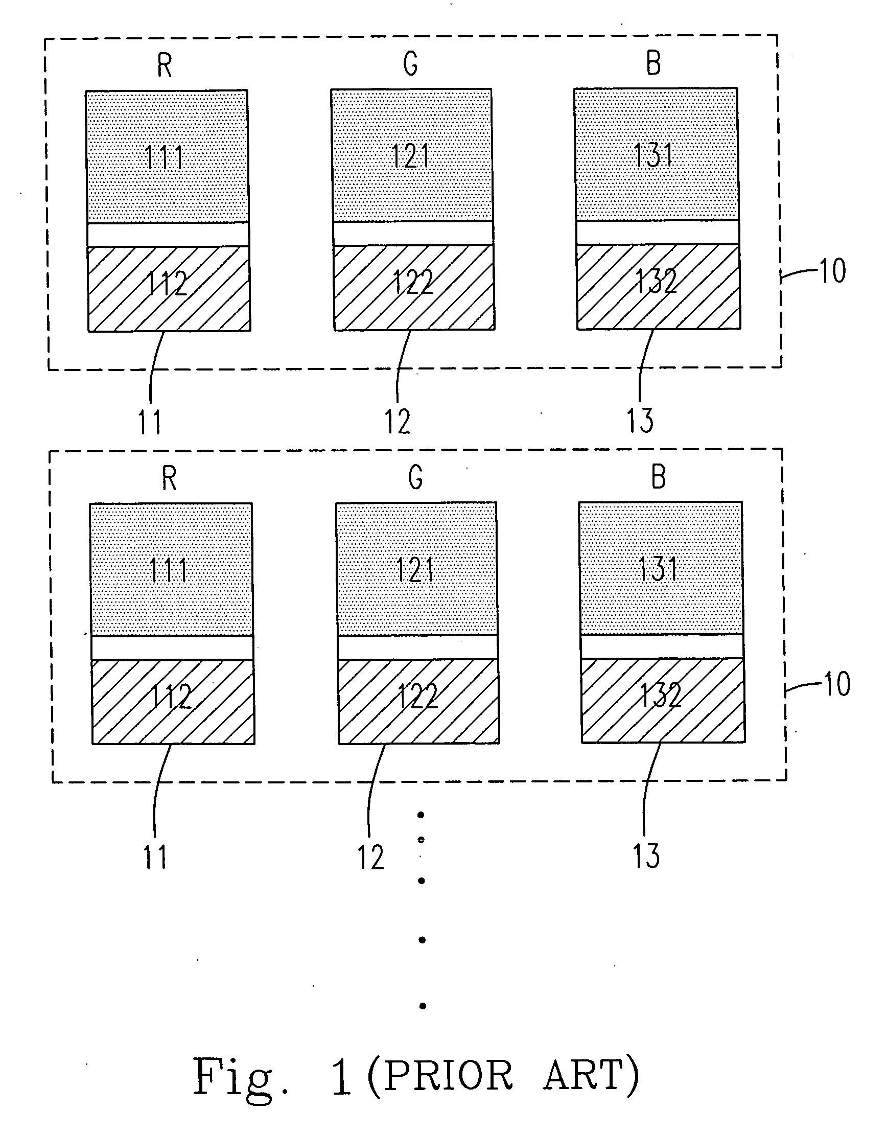
Thus, the color level and the brightness in the display are often limited to its light-emitting material with a relatively lower luminous efficacy.
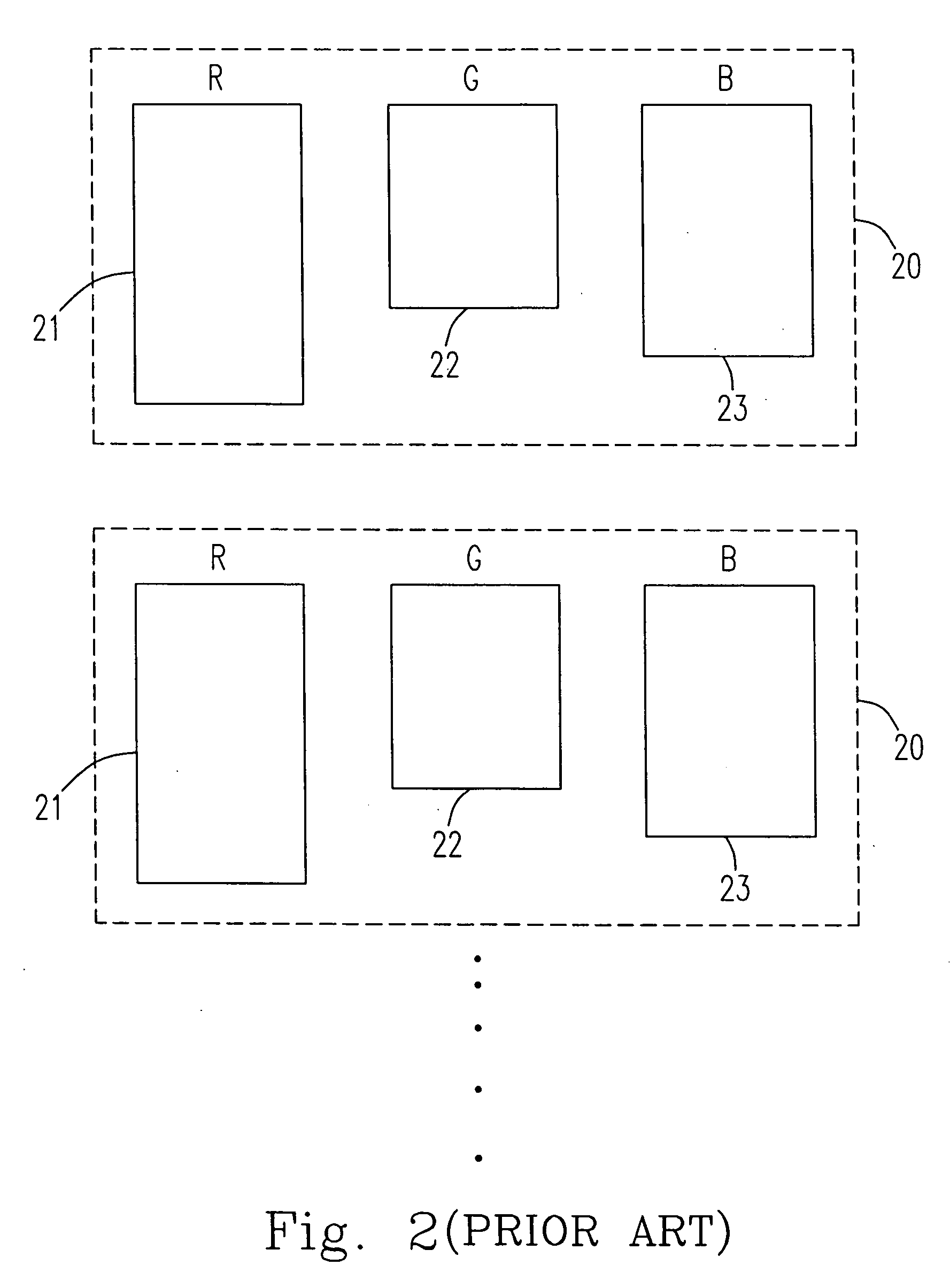
However, it would be quite difficult to achieve the above standard because of less light-emitting area and less driving current according to the conventional layout.

Method used


Image

  • Method and system for driving pixel in active matrix display
  • Method and system for driving pixel in active matrix display
  • Method and system for driving pixel in active matrix display

Examples


Embodiment Construction

[0050] The present invention will now be described more specifically with reference to the following embodiment. It is to be noted that the following descriptions of preferred embodiment of this invention are presented herein for purposes of illustration and description only; it is not intended to be exhaustive or to be limited to the precise form disclosed.

[0051] Different light-emitting materials respectively include different luminous efficacy in the present active display, so that the brightness in a respective sub-pixel of a single pixel is not identical. Thus, the brightness in the single pixel would be decreased because of the brightness in one sub-pixel with a relatively lower luminous efficacy. Therefore, the present invention would be implemented by re-configuring the driving layout of the sub-pixels in the single pixel to effectively enhance the brightness in the sub-pixels with different luminous efficacy, thereby enhancing the brightness in the display.

[0052] Please r...


PUM


Abstract

A pixel driving system in an active matrix display is provided. The system includes a first sub-pixel including a first transparent area and a first drive circuit area, and a second sub-pixel including a second transparent area and a second drive circuit area, in which the first drive circuit area is electrically connected to the second transparent area so as to drive the second sub-pixel for light-emitting, and the second drive circuit area is electrically connected to the first transparent area so as to drive the first sub-pixel for light-emitting. Further, a method for driving a pixel in an active matrix display is also provided.

Description

FIELD OF THE INVENTION [0001] The present invention is related to a method and a system for driving a pixel, and more particularly to a method and a system for driving a pixel to enhance the luminous brightness on the pixel in an active matrix display. BACKGROUND OF THE INVENTION [0002] Up to the present, the display (or “monitor”) has played an important role for communicating between the human and machine because the personal computer (PC), the network and other information medium have gained popularity with the technological progress. Further, the display industry has made substantially progress with the continuous research and development therefor. Thus, the novel display technologies such as a plasma display panel (PDP) and a liquid crystal display (LCD) which include a bigger, thinner and lighter size have substituted for the conventional cathode ray tube (CRT) monitor with a heavier and hunger volume. [0003] Nowadays, a new technique “organic light-emitting diode (OLED)” is d...

Claims


Application Information

Patent Timeline
IPC IPC(8): G09G5/00
CPCG09G3/3225G09G2300/0452
Inventor LIN, LICHILIN, YUHSIANG
Owner DELTA OPTOELECTRONICS
Learn More