
Deposition mask

a deposition mask and mask body technology, applied in the field of deposition masks, can solve the problems the difficulty of deposition material adhesion, and the instability of the deposition near the wall surface so as to reduce the thickness of the deposition mask, the effect of lowering the luminous efficacy of the organic el display device and the dimensional precision and/or positional precision of pixels

Active Publication Date: 2022-01-11
DAI NIPPON PRINTING CO LTD
View PDF23 Cites 0 Cited by
  • Summary
  • Abstract
  • Description
  • Claims
  • Application Information

AI Technical Summary

Benefits of technology

The present disclosure aims to prevent deposition masks from getting wrinkled when in contact with a deposition target substrate. This is achieved by reducing the thickness of the deposition mask and decreasing the ratio of deposition material that adheres to the wall surface of through holes in the deposition mask, which can lead to uneven deposition and lowered luminous efficacy of organic EL display devices. The technical effect of this disclosure is improved deposition precision and product quality.

Problems solved by technology

In this case, it is difficult for the deposition material to adhere to an area of the deposition target substrate, which is located near the wall surface of the through hole in the deposition mask.
Namely, it can be considered that deposition near a wall surface of a through hole in the deposition mask becomes unstable.
Thus, when a deposition mask is used for forming pixels of an organic EL display device, dimensional precision and / or positional precision of pixels may be lowered, which results in lowering of luminous efficacy of the organic EL display device.
However, a deposition mask having a smaller thickness, i.e., a thinned deposition mask is likely to get wrinkled, when it is brought into contact with a deposition target substrate.
In particular, when a deposition mask has a longitudinal direction and is suspended along the longitudinal direction, the deposition mask is likely to have wrinkles extending along the longitudinal direction.
The present inventors consider that the minute undulations generated in the width direction of the deposition mask make uneven a distance between the deposition mask and the magnet in the width direction of the deposition mask, which results in uneven timings at which the deposition mask is withdrawn to a deposition target substrate.

Method used


Image

  • Deposition mask
  • Deposition mask
  • Deposition mask

Examples


example 1

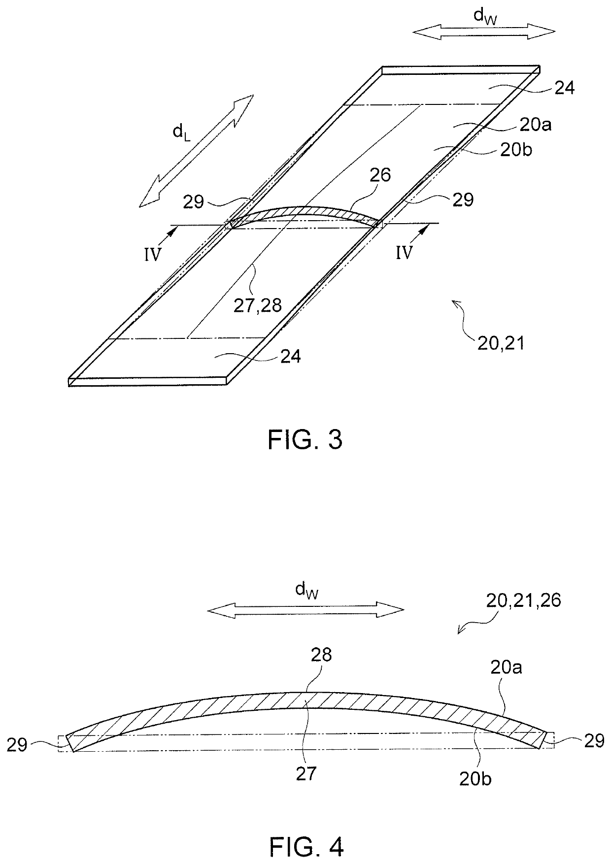
[0152]All the manufactured deposition masks were warped to be convex on the first surface providing a surface facing a deposition target substrate, in a cross section orthogonal to the longitudinal direction in the central portion in the longitudinal direction. D1 (mm) and D2 (mm) were measured for each deposition mask. To be specific, each deposition mask was placed on a horizontal flat surface such that the first surface faced upward, and a distance along the width direction between the first total pitch mark and the second total pitch mark that were closest to the center of the longitudinal direction, so as to obtain a value of D1 (mm). In addition, the deposition mask was placed on the horizontal flat surface such that the first surface faced upward, a glass plate is placed on the deposition mask from above, and a load is applied from the glass plate to the deposition mask so that the deposition mask was flattened. A distance along the width direction between the first total pit...

example 2

[0153]In each deposition mask, out of the plurality of through holes located closest to the edge on one side of the width direction of the deposition mask, a through hole closest to the center of the longitudinal direction was represented as a first through hole. In addition, out of the plurality of through holes located closest to the edge on the other side of the width direction of the deposition mask, a through hole whose separation distance to the first through hole along the longitudinal direction is shortest was represented as a second though hole. The deposition mask was placed on a horizontal flat surface such that the first surface faced upward, and a distance along the width direction between the first through hole and the second through hole was measured, so as to obtain a value of D1 (mm). In addition, the deposition mask was placed on the horizontal flat surface such that the first surface faced upward, a glass plate is placed on the deposition mask from above, and a lo...


PUM

PropertyMeasurementUnit
distanceaaaaaaaaaa
distanceaaaaaaaaaa
thicknessaaaaaaaaaa

Abstract

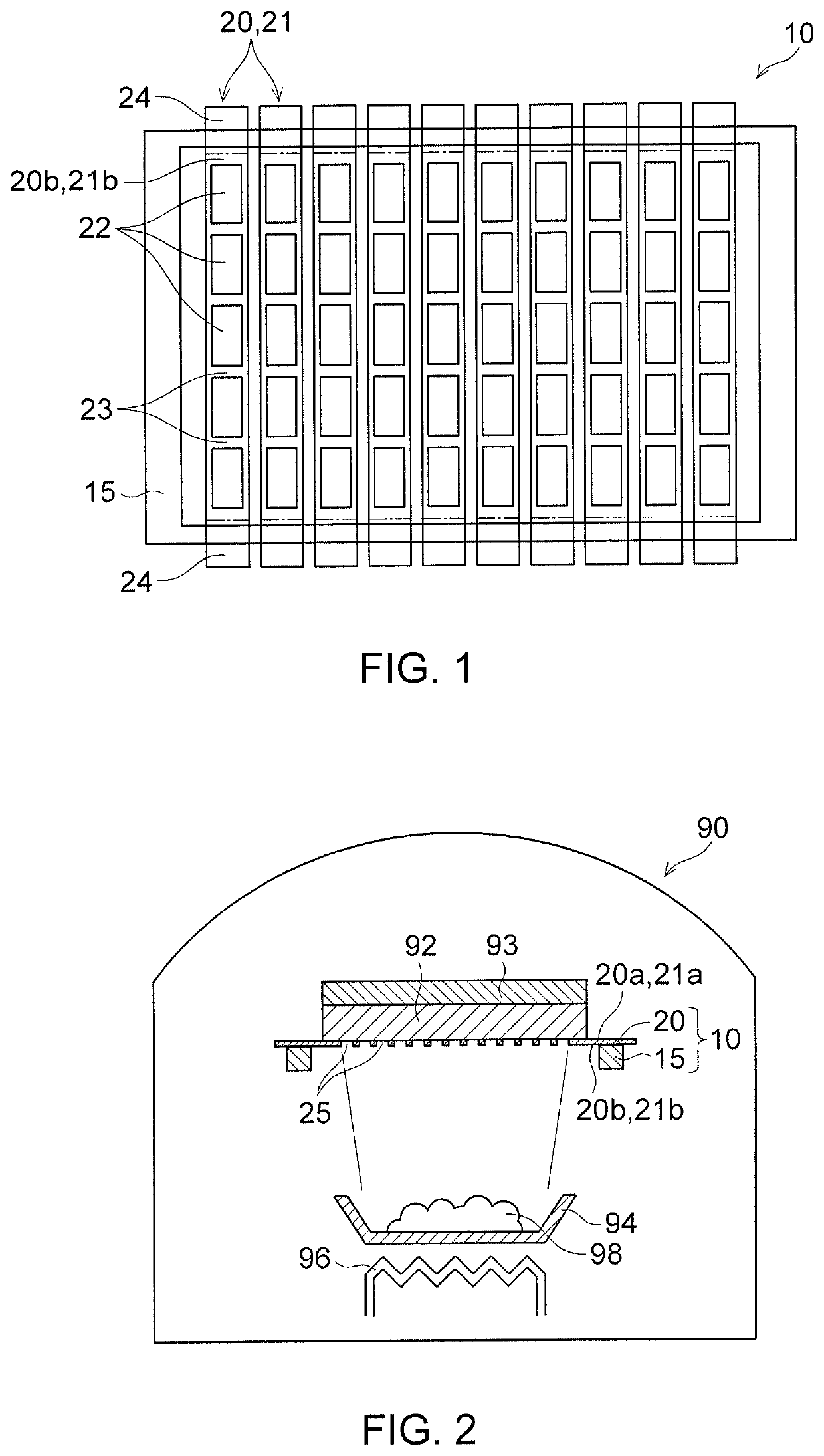
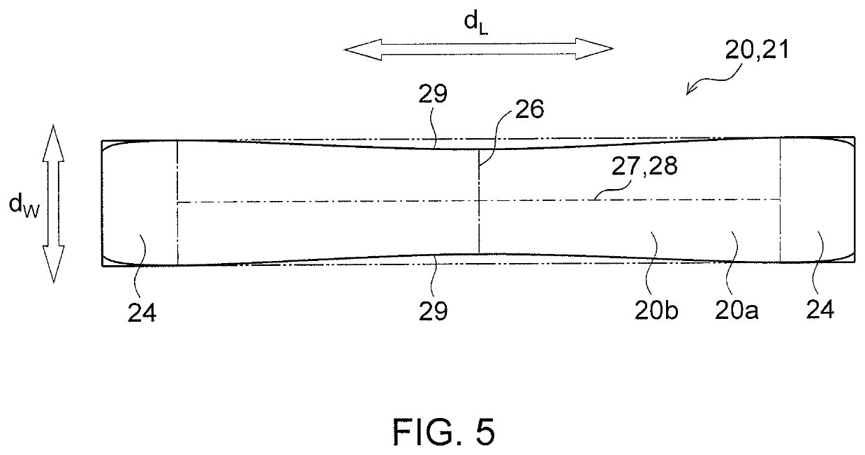
A deposition mask includes a first surface facing to the deposition target substrate, and a second surface opposite to the first surface. The deposition mask includes: an effective area in which a plurality of through holes are formed and a longitudinal direction in which one or more of the effective areas are arranged along the longitudinal direction. At least in a central area of the longitudinal direction, the deposition mask is warped to be convex on the first surface in a cross section orthogonal to the longitudinal direction.

Description

CROSS-REFERENCE TO RELATED APPLICATIONS[0001]This application is based upon and claims the benefit of priority from Japanese Patent Application No. 2016-225435, filed on Nov. 18, 2016; the entire contents of which are incorporated herein by reference.TECHNICAL FIELD[0002]The present disclosure relates to a deposition mask that is used when a deposition material is deposited onto a deposition target substrate in a desired pattern.BACKGROUND ART[0003]A display device used in a portable device such as a smart phone and a tablet PC is required to have high fineness, e.g., a pixel density of not less than 500 ppi. In addition, there is increasing demand that the portable device is applicable in the ultra high-definitions (UHD) reference. In this case, the pixel density of the display device needs to be not less than 800 ppi or more, for example.[0004]An organic EL display device draws attention because of its excellent responsibility, low power consumption and excellent contrast. A known...

Claims


Application Information

Patent Timeline
Patent Type & Authority Patents(United States)
IPC IPC(8): C23C14/04C23F1/02C23C14/24H01L51/00H01L51/56H10K99/00
CPCC23C14/042C23C14/04C23F1/02C23C14/24H01L51/0011H01L51/56H10K71/00H10K71/166H05B33/10
Inventor IKENAGA, CHIKAO
Owner DAI NIPPON PRINTING CO LTD
Learn More