Exposure apparatus and device manufacturing method

a technology of exposure apparatus and manufacturing method, which is applied in the direction of microlithography exposure apparatus, printers, instruments, etc., can solve the problems of thermal deformation of substrate, insufficient focus margin during exposure operation, and adversely affecting the pattern to be formed on the substra

Inactive Publication Date: 2006-07-13
NIKON CORP
View PDF98 Cites 32 Cited by
  • Summary
  • Abstract
  • Description
  • Claims
  • Application Information

AI Technical Summary

Benefits of technology

[0013] In accordance with the present invention, because it is configured such that a liquid is supplied from above the substrate in a state that the entire substrate is immersed in the liquid, the influence of the vaporization of the liquid on the substrate surface, specifically, e.g., the thermal deformation of the substrate and the emergence of an adhesion trace due to the liquid vaporization, can be prevented, and because a fresh and clean liquid can be supplied between the projection optical system and the substrate, the influences of the liquid temperature change and of impurities being suppressed, thereby a desired pattern can be formed on the substrate. Thus, devices having a desired performance can be manufactured.
[0015] In accordance with the present invention, by detachably setting the substrate holding member on the movable member, the substrate having experienced an exposure process can be carried out in a state that the substrate is held by the substrate holding member. Accordingly, the ambient condition change, the rusting of the devices, etc., caused by the dropping or scattering of the liquid from the substrate can be prevented.
[0017] In accordance with the present invention, because by detachably setting the substrate holding member on the movable member, a substrate having experienced an exposure process can be carried out in a state that the substrate is held by the substrate holding member, the adhesion and residual of the liquid on the movable member or the members near the movable member can be prevented, and, for example, the dropping of the liquid from the substrate can be prevented.
[0018] A device manufacturing method of the present invention uses the exposure apparatuses described above. In accordance with the present invention, devices having a desired performance can be manufactured in a state that the influence of the vaporization of the liquid and the ambient condition change are suppressed.

Problems solved by technology

When the depth of focus δ becomes too narrow, it becomes difficult to make the substrate surface coincide with the image plane of the projection optical system, and thus there occurs the possibility that the focus margin during the exposure operation will be insufficient.
WO 99 / 49504 is configured such that a liquid is supplied and recovered so that a liquid immersion region is formed on a part of a substrate; however, when the liquid is not completely recovered and remains on the substrate, there is the possibility that the remaining liquid vaporizes, thereby the substrate thermally deforms and, after vaporizing, an adhesion trace (so-called water mark) remains on the substrate and adversely affects the pattern to be formed on the substrate.
H10-303114 is configured such that the entirety of a substrate is held in a liquid; however, because the liquid between the projection optical system and the substrate is not replaced so much, there is the possibility that the temperature of the liquid of the liquid immersion region may change and impurities are apt to be contained therein, which may deteriorates the pattern image projected onto the substrate.
Thus, there arises the possibility that devices having a desired performance cannot be manufactured.
WO 99 / 49504, when a substrate having experienced an exposure process is conveyed (carried out), with the liquid remaining (adhering) on the surface of the substrate, the remaining liquid drops from the substrate during the conveyance process, which results, for example, the disadvantage that due to the liquid dropped, various devices and members neighboring on the conveyance path rust, or the cleanliness of the ambience in which the exposure apparatus is installed cannot be maintained.
Furthermore, the liquid that has dropped (scattered) from the substrate may cause the ambient condition (humidity) change around the exposure apparatus.
When the humidity changes, there arises, for example, the problem that the air on the optical path of an optical interferometer used for measuring the stage position fluctuates, the stage measurement cannot be performed accurately, and thus a desired pattern transfer accuracy cannot be obtained.
Furthermore, if after the exposure process, a development process, for example, is performed in a state that the liquid still adheres on the substrate, there arises the possibility that devices having a desired performance cannot be manufactured.

Method used


Image

  • Exposure apparatus and device manufacturing method
  • Exposure apparatus and device manufacturing method
  • Exposure apparatus and device manufacturing method

Examples


Embodiment Construction

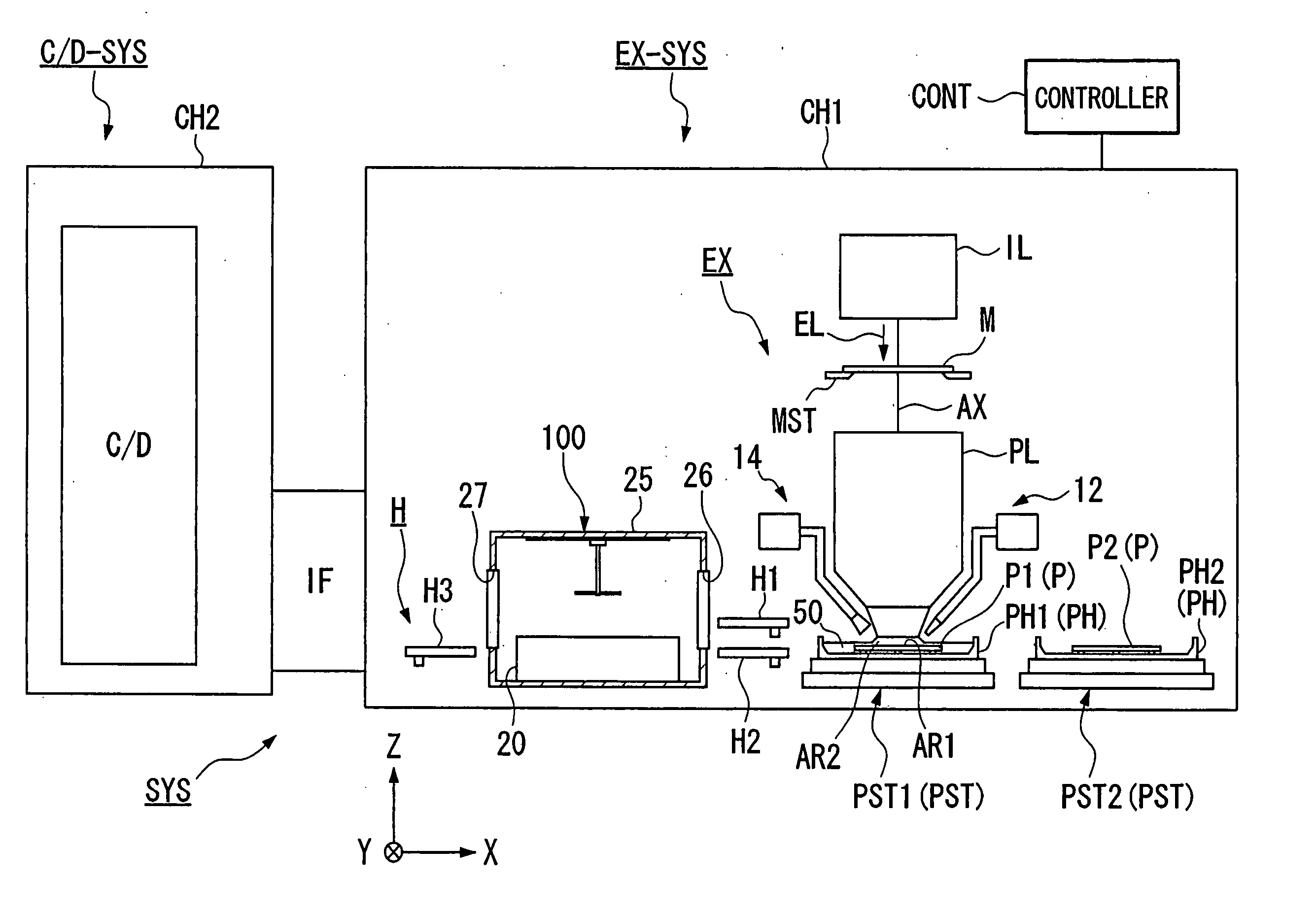
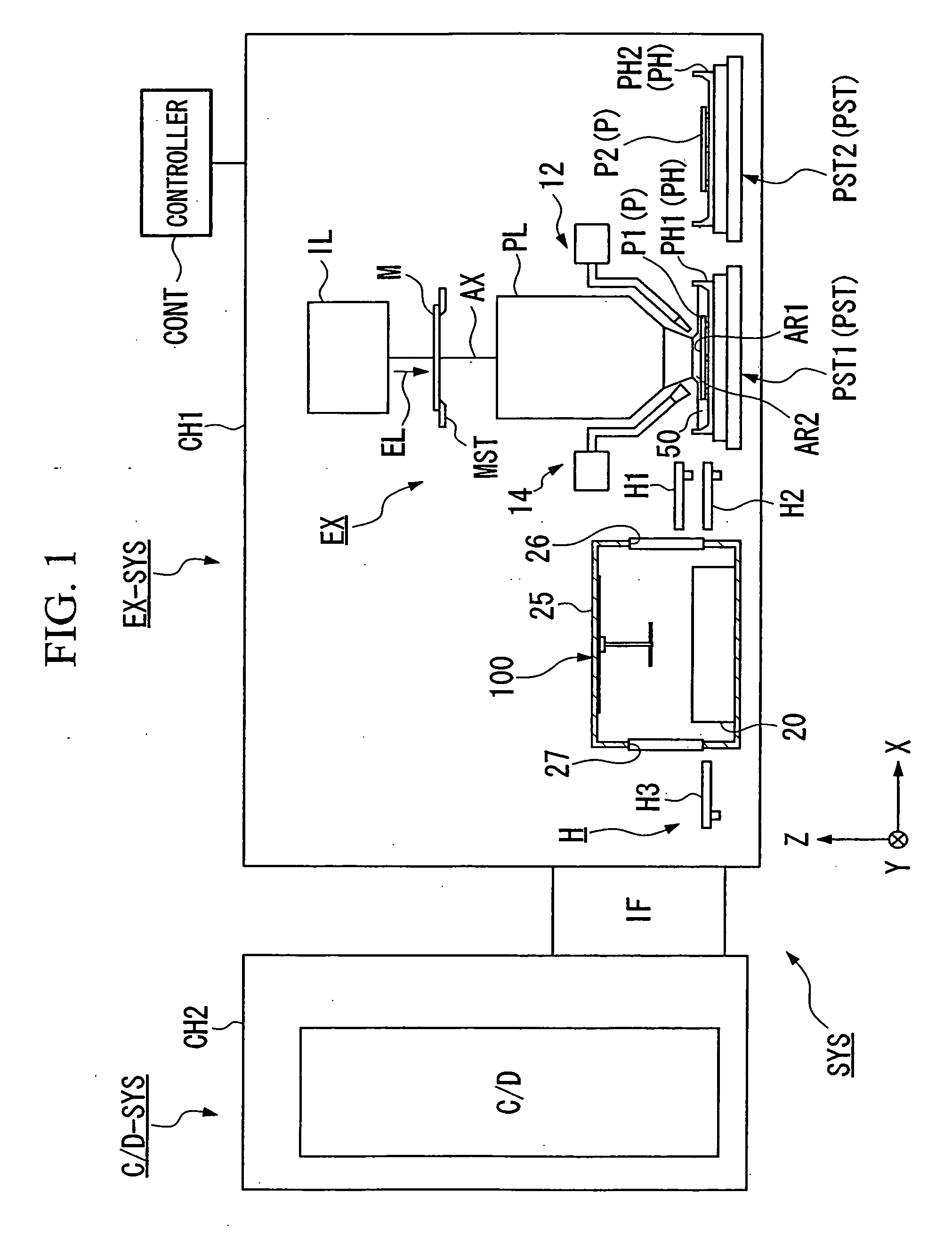
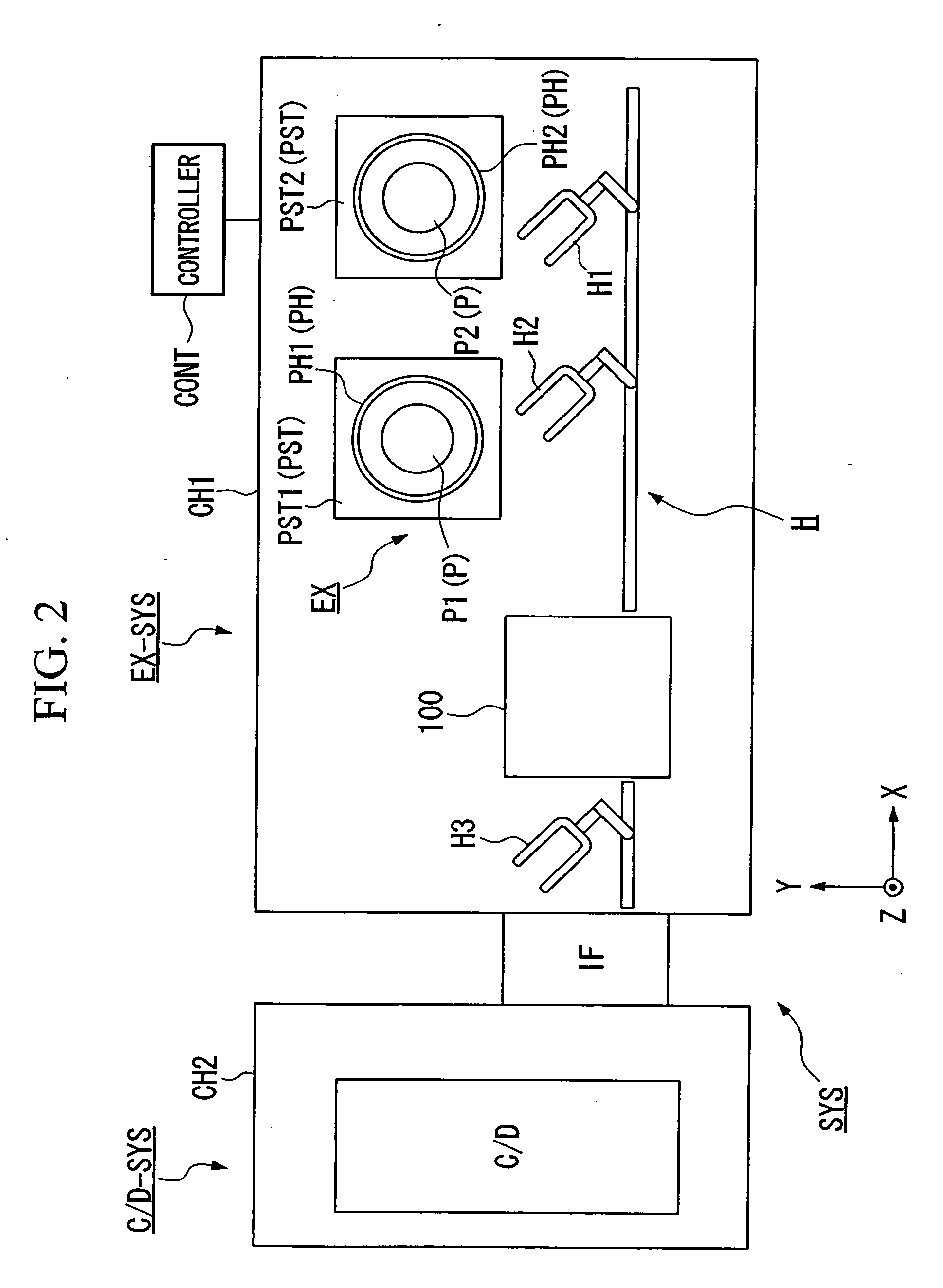
[0031] Now, referring to the drawings, an exposure apparatus and a device manufacturing method of the present invention will be described. FIG. 1 is a drawing showing an embodiment of a device manufacturing system provided with an exposure apparatus of the present invention and is a schematic diagram when viewed from the side; FIG. 2 is a drawing when FIG. 1 is viewed from above.

[0032] In FIGS. 1 and 2, a device manufacturing system SYS is provided with an exposure apparatus EX-SYS and a coater-developer device C / D-SYS. The exposure apparatus EX-SYS is provided with an interface portion IF that forms a connection portion thereof to the coater-developer device C / D-SYS, with an exposure apparatus main body EX that by filling a space between a projection optical system PL and a substrate P, an object to be exposed, with liquid 50 and by projecting a pattern image onto the substrate P via the projection optical system PL and the liquid 50, exposes the substrate P, with a conveyance sys...


PUM

PropertyMeasurementUnit
wavelengthaaaaaaaaaa
refractive indexaaaaaaaaaa

Abstract

An exposure apparatus in which by filling at least a portion between a projection optical system and a substrate with a liquid and by projecting an image of a pattern onto the substrate via said projection optical system and said liquid, said substrate is exposed, said exposure apparatus includes: a substrate holding member that holds said substrate and keeps liquid so that said substrate is immersed in the liquid; and a liquid supply mechanism that supplies, at a vicinity of the projection area of said projection optical system, liquid onto said substrate from above said substrate.

Description

CROSS-REFERENCE TO RELATED APPLICATION [0001] This is a Division of U.S. patent application Ser. No. 11 / 270,548 filed Nov. 10, 2005, which in turn is a Continuation of International Application No. PCT / JP2004 / 006853, filed May 14, 2004, which claims priority to Japanese Patent Application No. 2003-137214, filed May 15, 2003. The contents of the aforementioned applications are incorporated herein by reference in their entireties.BACKGROUND OF THE INVENTION [0002] 1. Field of the Invention [0003] The present invention relates to an exposure apparatus in which with at least a portion between a projection optical system and a substrate being filled with a liquid, a pattern is exposed onto the substrate via the projection optical system and the liquid, and to a device manufacturing method that uses the exposure apparatus. [0004] 2. Description of Related Art [0005] Semiconductor devices and liquid crystal display devices are manufactured through the so-called photolithography technique, ...

Claims


Application Information

Patent Timeline
Patent Type & Authority Applications(United States)
IPC IPC(8): G03B27/42G03F7/20
CPCG03F7/70341G03F7/707G03F7/7075
Inventor ISHII, YUUKI
Owner NIKON CORP
Why Eureka
Try Eureka