
Automated energy management system

a technology of energy management and automatic control, applied in the direction of material dimension control, process and machine control, instruments, etc., can solve the problems of increasing the difficulty of implementing demand shaving, the difficulty of reducing capacity kw, and the complexity of the reduction technique of kw, so as to achieve a greater level of energy efficiency

Inactive Publication Date: 2006-07-13
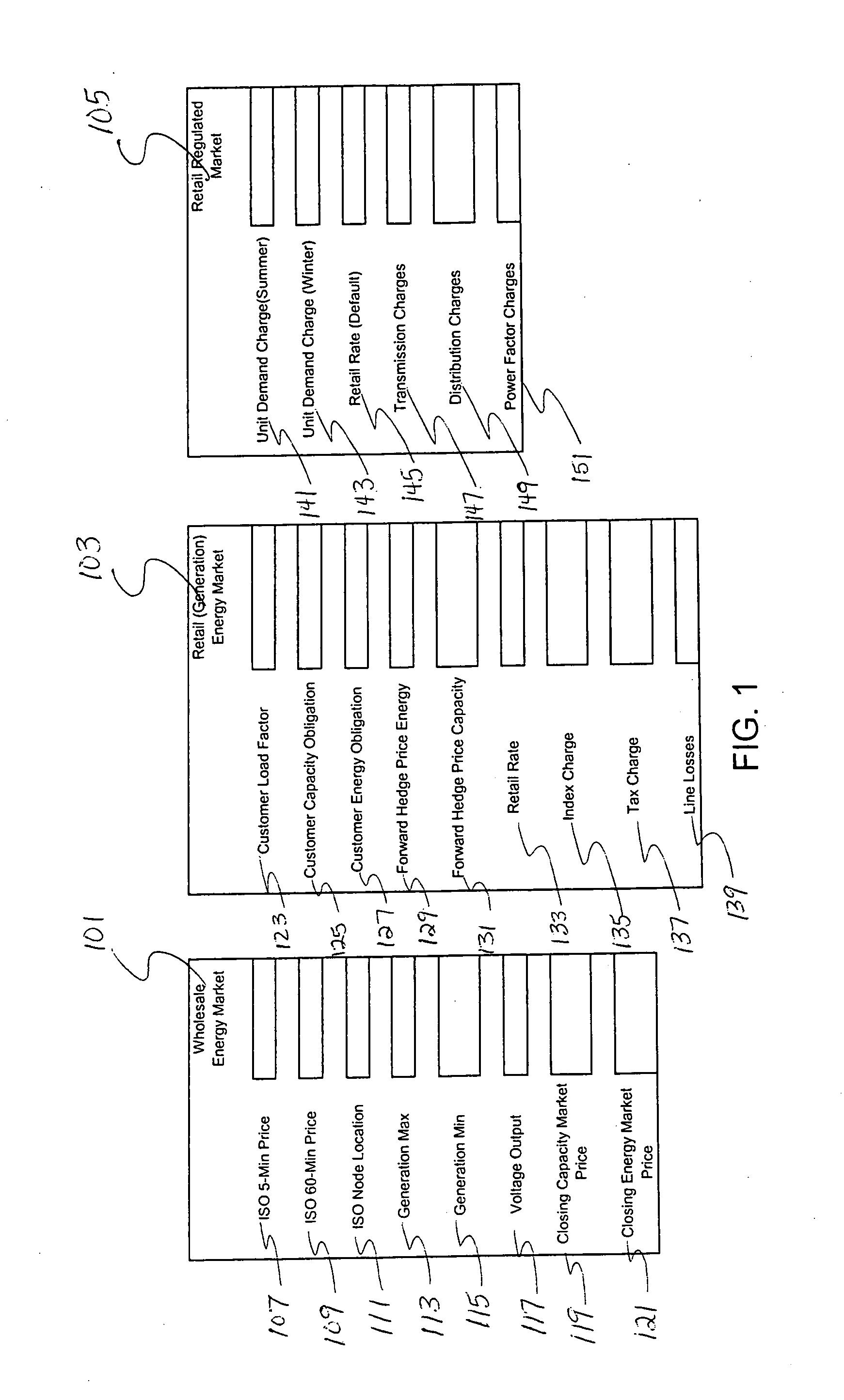
BUDIKE LOTHAR E S JR
View PDF6 Cites 140 Cited by
  • Summary
  • Abstract
  • Description
  • Claims
  • Application Information

AI Technical Summary

Benefits of technology

[0019] An advantage of the invention, is that it provides an energy management system that optimizes and merges supply side procurement with demand side management in order to ultimately provide consumers a greater level of energy efficiency.

Problems solved by technology

Capacity (kW) reduction techniques are more complicated.
Again, more limited, there exists prior art for devices and methods to “peak-shave” demand.
Capacity kW reductions are slightly harder to manage.
Demand shaving has been the harder of the two to implement due to the fact that monitoring equipment and reaction time needed to be addressed in order to reduce the demand within the utilities billing window of 15 to 30 minutes.
Due to the volatility in the energy market, energy suppliers can be exposed to energy prices in the spot market that are extremely high.
The problem is that the consumer is now paying this surcharge year around for a risk that may happen only 60 hours per year.
For example, a steel mill that produces steel bars uses enormous amounts of electricity to produce the steel.
Unfortunately, 99% of all commercial consumers do not have the option to shut down for a period of time nor do they have automated means for controlling load to hedge against the risk of volatile spot market pricing.
When performing supply side energy management of buildings, there is quite a limited base of related technical art that can perform such type of management.
However, regardless of whether the consumer elects to perform a demand or a supply side energy management program, the consumer is still at a great disadvantage in achieving maximum savings potential because the two processes are independent of each other.
The demand side strategy saves net dollars from reduced kWh usage but with the sheer dynamics of the energy supplier's rate structure, the consumer never really knows “when” is the best time to manage their demand side energy usage in order to directly impact the suppliers price of power.

Method used


Image

  • Automated energy management system
  • Automated energy management system
  • Automated energy management system

Examples


Embodiment Construction

[0030] Reference will now be made in detail to an embodiment of the invention, an example of which is illustrated in the accompanying drawings.

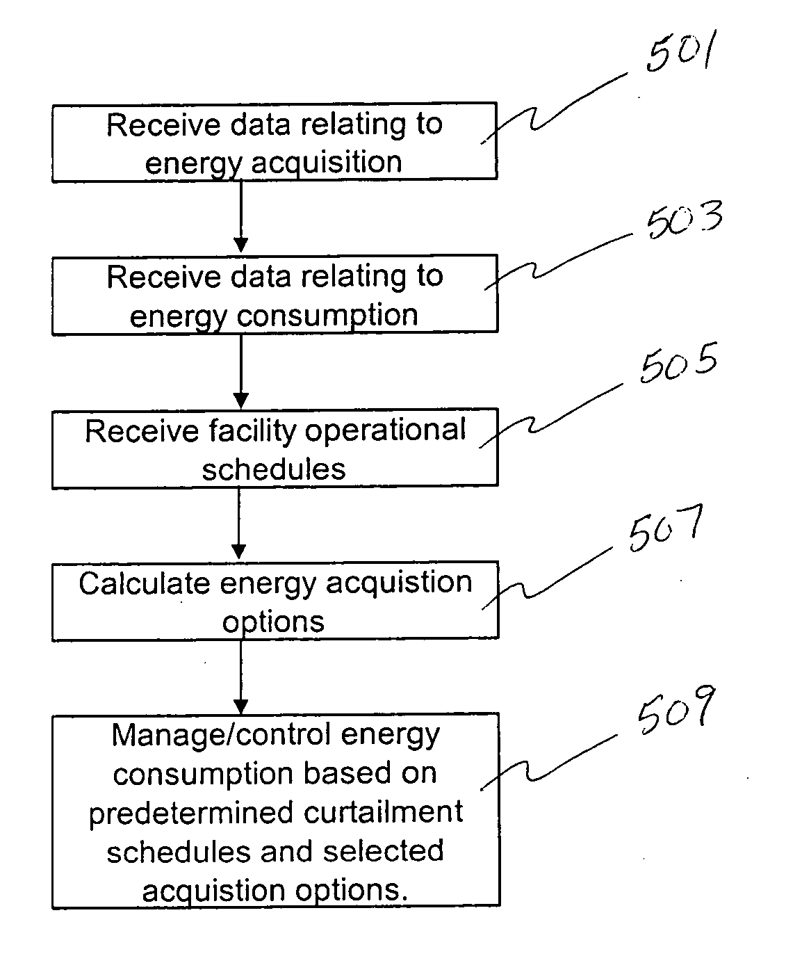
[0031] The invention relates to an automated energy rate reduction and demand side sequencing management and analysis system utilized to drive further energy saving efficiencies for commercial consumers by bridging the gap between supply and demand side energy management. This management system enables energy consumer's to determine, automate and react in “real-time” to all of the cost sensitive energy billing components in a unregulated or regulated utility energy supplier rate as well as determine a “real-time” demand side operational sequence in order to drive new costs in their facility.

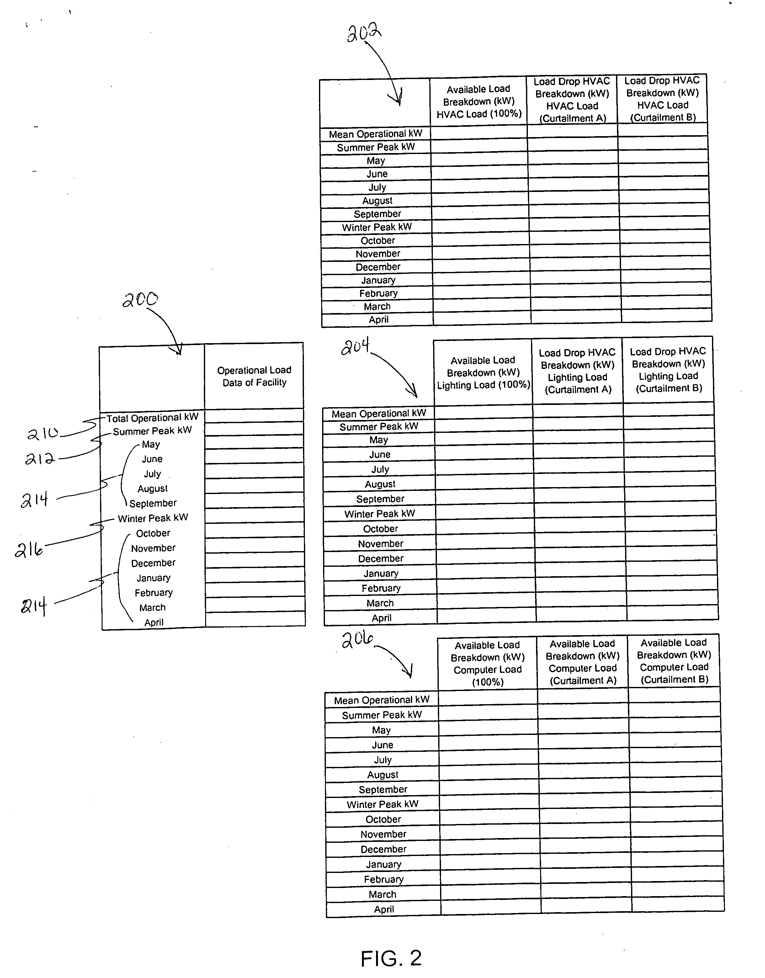
[0032] The energy management system according to an embodiment of the invention processes and analyzes different input data regarding consumers' supply side energy pricing and demand side operational control sequences for the facility (“savings aggressiv...


PUM


Abstract

An automated energy rate reduction and demand side sequencing management and analysis system bridges the gap between supply and demand side energy management. The management system enables energy consumer's to determine, automate and react in “real-time” to all of the cost sensitive energy billing components in a unregulated or regulated utility energy supplier rate as well as determine a “real-time” demand side operational sequence in order to drive new costs in their facility.

Description

BACKGROUND OF THE INVENTION [0001] 1. Field of the Invention [0002] The invention relates to energy management, and more particularly to a system for providing both supply and demand side energy management. [0003] 2. Discussion of the Related Art [0004] In order to understand the dynamics of energy pricing structures it is important to understand the difference between the two fundamental components in electricity, energy and capacity. Energy suppliers purchase these two energy components in the wholesale energy market in order to serve their customers. [0005] Energy is the amount of power used over a specific period of time usually measure as kilowatts per hour (kWh). If an analogy was being formed to describe energy, think of the odometer of a car. If the car is moving, energy relates to the odometer reading, i.e., the number of miles the car has moved. It makes no difference about the speed of the car, the consumer pays for the movement of the car from point A to Point B, what yo...

Claims


Application Information

Patent Timeline
IPC IPC(8): G06F19/00
CPCG06Q10/06G06Q50/06
Inventor BUDIKE, LOTHAR E. S. JR.
Owner BUDIKE LOTHAR E S JR
Learn More