Omnidirectional wireless pedometer

a wireless pedometer and wireless technology, applied in the direction of distance measurement, mechanical measurement arrangement, instruments, etc., can solve the problems of poor signal reception, and poor signal reception of receiving antenna and transmitting antenna

Inactive Publication Date: 2006-07-13
CHEN YU YU
View PDF3 Cites 2 Cited by
  • Summary
  • Abstract
  • Description
  • Claims
  • Application Information

AI Technical Summary

Benefits of technology

[0015] Thus, a primary object of the present invention is to provide an omnidirectional wireless pedometer which is capable to receive signal in all directions. It is not necessary to maintain the transmitting antenna in parallel position relative to that of the receiving antenna.

Problems solved by technology

However, it is not easy to maintain the relatively parallel positions of the receiving antenna and the transmitting antenna.
Inevitably, the receiving antenna receives poor signal, or even no signal.
It is found that poor reception of signal is remarkable especially when the wireless signal transmission technique is applied in dynamic applications.
Hence, the receiver cannot be maintained in a parallel position relative to the transmitter for optimal signal reception.
Hence, the signal cannot be effectively received.
When the receiver is located far from the transmitter, the received signal is very weak, and it is not able to decode and recognize the signal, especial two wireless pedometers walking along.
Similarly, the signal cannot be decoded and is not readable.
(4) In practical application, the signal is enhanced in some directions, but the signal is also weakened or interfered in other directions, especial two / the people walking along.

Method used


Image

  • Omnidirectional wireless pedometer
  • Omnidirectional wireless pedometer
  • Omnidirectional wireless pedometer

Examples


Embodiment Construction

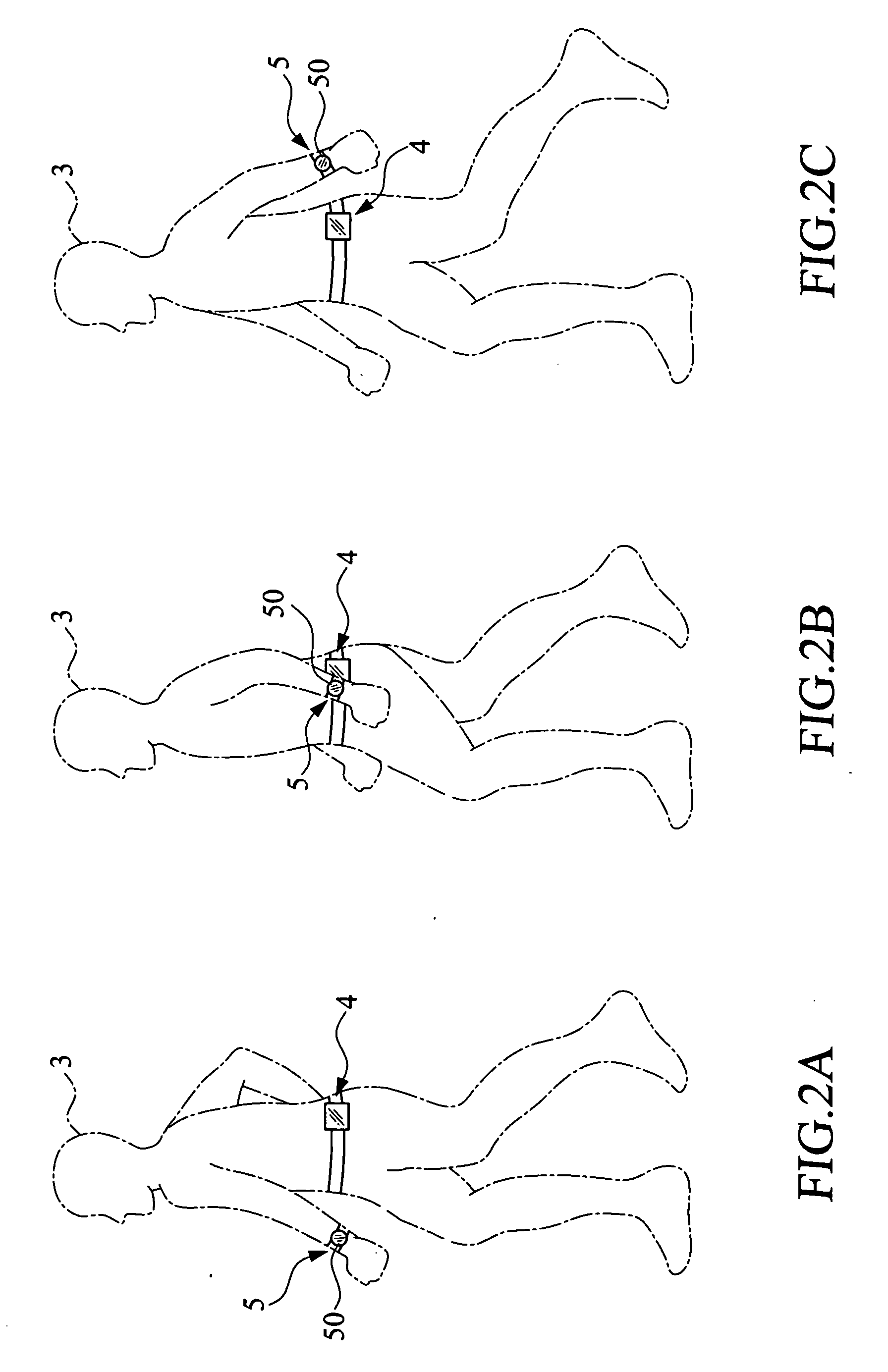
[0026] Please refer to the drawings and in particular to FIGS. 2A to 2C which show that an omnidirectional wireless pedometer constructed in accordance with the present invention is fitted to a user who is walking. The omnidirectional wireless pedometer comprises a wireless transmitter 4 and a wireless receiver 5. The wireless transmitter 4 is fitted around the waist of the user 3 or any part of the body, and the wireless receiver 5 is fitted to the wrist of the user 3. A display unit which may comprises a LCD 58 is arranged on the wireless receiver 5 for displaying the pace signal received from the receiver 5.

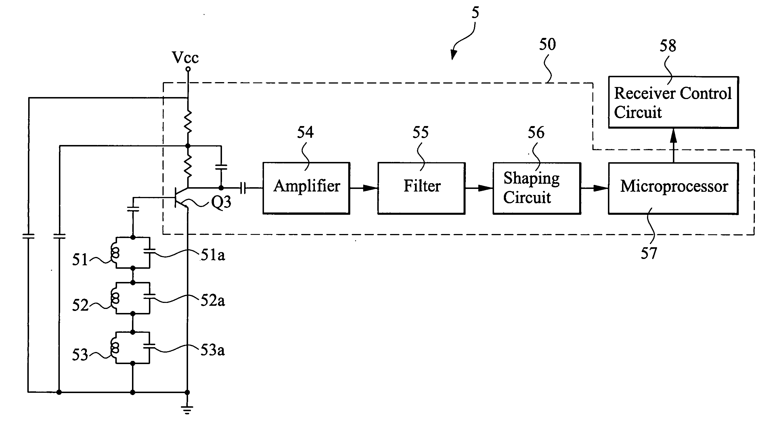
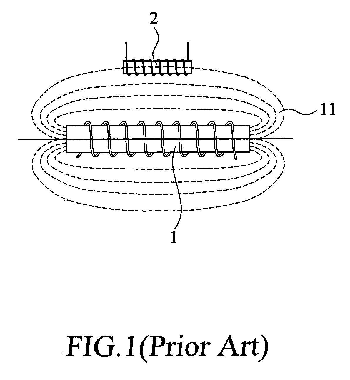
[0027]FIG. 3 is a schematic view showing the arrangement of three receiving antennas in the receiver for receiving the magnetic field transmitted by the transmitter. The transmitter 4 comprises a single transmitting antenna 41, while the receiver 5 comprises three series receiving antennas 51, 52, 53 arranged in three different directions.

[0028] To optimize signal reception,...


PUM


Abstract

An omnidirectional wireless pedometer includes a transmitter and a receiver. The transmitter includes a vibration sensor, a transmitter control circuit, an oscillating circuit and a transmitting antenna. The vibration sensor detects a vibration signal when a user walks or jogs and transmits the vibration signal to the transmitter control circuit. Then, the vibration signal is transmitted to the oscillating circuit which generates an oscillating signal and forwards the oscillating signal to the transmitting antenna for transmitting out wirelessly. The receiver comprises three receiving antennas respectively arranged in X, Y, and Z directions. The receiving antennas are capable to receive pace signal from different directions and generate a resonance signal. Subsequently, the resonance signal is transmitted to a receiver control circuit for processing, which generates a data signal to be displayed in a displayed unit.

Description

FIELD OF THE INVENTION [0001] The present invention relates to a wireless motion monitoring device, and more particularly, to a wireless pedometer fitting around a user's waist for receiving pace signal in all directions. BACKGROUND OF THE INVENTION [0002] There are a variety of body building devices and exercisers developed for people who live busily in the modern commercial society and require appropriate exercises. For a person to accurately control a moderate amount of exercise and monitor personal physical condition, various types of body / motion signal sensing devices have been researched and developed. [0003] Among the various motion signal sensing devices, pedometer is the most extensively used. Pedometer is generally compact, convenient for taking along and simple for use, which is capable to measure the accumulated number of paces that a user advances at, for example, walking or jogging. There are many kinds of pedometers in the market. Some of the pedometers are able to re...

Claims


Application Information

Patent Timeline
Patent Type & Authority Applications(United States)
IPC IPC(8): G01C22/00G01B11/02G01B11/14
CPCG01C22/006
Inventor CHEN, YU-YU
Owner CHEN YU YU
Why Eureka
Try Eureka